Download
1 / 25

E N D
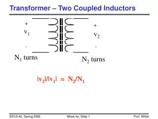
Inductors Chap 11
Magnetic fields • A magnetic field may be represented by a mathematical description of the magnetic influence of electric currents and magnetic materials. The magnetic field at any given point is specified by both a direction and a magnitude (or strength); as such it is a vector field • Magnetic fields are produced by moving electric charges and the intrinsic magnetic moments of elementary particles Electromagnetism Magnetic field of an ideal cylindrical magnet with its axis of symmetry inside the image plane. Compasses reveal the direction of the local magnetic field.
Magnetic fields • The magnetic flux is measured in webers (Wb) and the applied symbol is the capital Greek letter phi Φ Flux density
Example • For the core determine the flux density B in teslas. • if the flux density is 1.2 T and the area is 0.25 in^2 , determine the flux through the core. However, converting 0.25 in.2 to metric units,
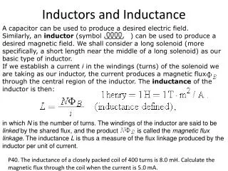
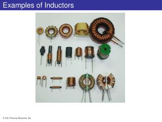
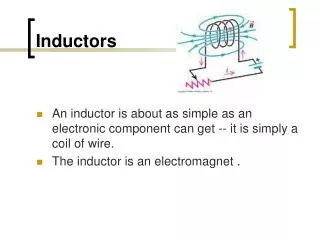
Inductors • Inductors are coils of various dimensions designed to introduce specified amounts of inductance into a circuit. • The inductance of a coil varies directly with the magnetic properties of the coil. • Ferromagnetic materials, are frequently employed to increase the inductance by increasing the flux linking the coil. • Inductance is measured in Henries (H) • 1 Henry is the inductance level that will establish a voltage of 1 volt across the coil
Inductors • An inductor is a passive two-terminal electrical component that stores energy in its magnetic field. • An inductor is typically made of a wire or other conductor wound into a coil, to increase the magnetic field. • When the current flowing through an inductor changes, creating a time-varying magnetic field inside the coil, a voltage is induced, according to Faraday's law of electromagnetic induction • Inductors are one of the basic components used in electronics where current and voltage change with time, due to the ability of inductors to delay and reshape alternating currents.
Inductors Inductor symbols
FARADAY’S LAW OFELECTROMAGNETIC INDUCTION If a conductor is moved through a magnetic field so that it cuts magnetic lines of flux, a voltage will be induced across the conductor The greater the number of flux lines cut per unit Time or the stronger the magnetic field strength, the greater will be the induced voltage across the conductor. Equation for voltage induced across a coil if a coil of N turns is placed in the region of a changing flux Increase the number of magnetic flux lines by increasing the speed with which the conductor passes through the field
Faraday’s law induced voltage equation N = number of turns of the coil = is the instantaneous change in flux (in webers) If the flux linking the coil ceases to change & Equation for inductance of the coils N = number of turns µ = permeability of the core A = area of the core in square meters l = the mean length of the core in meters. µ is not a constant but depends on the level of B and H, since µ = B/H
Substituting µ = µr µo into Equation we get Lo is the inductance of the coil with an air core
Example 11.1 For the air-core coil Find the inductance
Example 11.1 cont’ b) Find the inductance if a metallic core with µr = 2000 is inserted in the coil
In class exercise 1 Use equation for inductance of the coils Find the inductance of the air-core coil L
In class exercise 1 part2 • Repeat In class exercise 1 , but with an iron core and conditions such that µr = 2000. Use equation
In class exercise 1 part2 • Repeat In class exercise 1 , but with an iron core and conditions such that µr = 2000. We found in part 1 that Lo = 1.58 µH, so
Example 11.2 • If each inductor in the left column is changed to the type appearing in the right column, find the new induced level for each change, assume that the other factors remain the same. (a) The only change was the number of turns, but it is a square factor, resulting in L = The area is 3 times the original size increasing the inductance by a factor of 3. The number of turns is ½, which is reduced by (½ )^2 = ¼ .
Example 11.2 cont’ = 43.2 mH µ and the number of turns increased have increased, the increased length reduces inductance
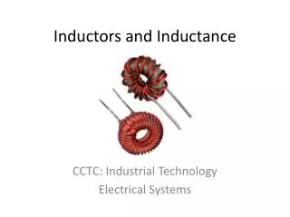
Types of Inductors • Inductors like Capacitor can be fixed or variable
HW • Problem# 1, 3, 5 & 7