Machining Tools and Techniques for Turning Operations
Explore various tools like collets, mandrels, and CNC lathes for turning operations. Learn about screw threads, complex shapes, and surface roughness. Understand dimensional tolerances and troubleshooting tips.

Machining Tools and Techniques for Turning Operations
E N D
Presentation Transcript
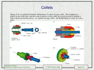
Collets Figure 22.6 (a) and (b) Schematic illustrations of a draw-in type collet. The workpiece is placed in the collet hole, and the conical surfaces of the collet are forced inward by pulling it with a draw bar into the sleeve. (c) A push-out type collet. (d) Workholding of a part on a face plate.
Mandrels Figure 22.7 Various types of mandrels to hold workpieces for turning. These mandrels are usually mounted between centers on a lathe. Note that in (a), both the cylindrical and the end faces of the workpiece can be machined, whereas in (b) and (c), only the cylindrical surfaces can be machined.
Swiss-Type Automatic Screw Machine Figure 22.8 Schematic illustration of a Swiss-type automatic screw machine. Source: George Gorton Machine Company.
Turret Lathe Figure 22.9 Schematic illustration of the components of a turret lathe. Note the two turrets: square and hexagonal (main). Source: American Machinist and Automated Manufacturing.
Computer Numerical Control Lathe Figure 22.10 A computer numerical control lathe. Note the two turrets on this machine. Source: Jones & Lamson, Textron, Inc.
(a) (b) Examples of Turrets Figure 22.11 (a) A turret with six different tools for inside-diameter and outside-diameter cutting and threading operations. (b) A turret with eight different cutting tools. Source: Monarch Machine Tool Company.
Examples of Parts Made on CNC Turning Machine Tools Figure 22.12
Examples of Machining Complex Shapes Figure 22.13
Surface Roughnesses Figure 22.14 The range of surface roughnesses obtained in various machining processes. Note the wide range within each group, especially in turning and boring. See also Fig. 26.4.
Dimensional Tolerances Figure 22.15 The range of dimensional tolerances obtained in various machining processes as a function of workpiece size. Note that there is an order of magnitude difference between small and large workpieces. Source: Adapted from Manufacturing Planning and Estimating Handbook, McGraw-Hill, 1963.
Examples of Threads Figure 22.16 (a) Standard nomenclature for screw threads. (b) Unified National thread and identification of threads. (c) ISO metric thread and identification of threads.
Types of Screw Threads Figure 22.17 Various types of screw threads.
Cutting Screw Threads Figure 22.18 (a) Cutting screw threads on a lathe with a single-point cutting tool. (b) Cutting screw threads with a single-point tool in several passes, normally utilized for large threads. The small arrows in the figures show the direction of feed, and the broken lines show the position of the cutting tool as time progresses. Note that in radial cutting, the tool is fed directly into the workpiece. In flank cutting, the tool is fed into the piece along the right face of the thread. In incremental cutting, the tool is first fed directly into the piece at the center of the thread, then at its sides, and finally into the root. (c) A typical carbide insert and toolholder for cutting screw threads. (d) Cutting internal screw threads with a carbide insert. (See also Figs. 21.2 and 21.3.)