Download
1 / 19
190 likes | 346 Views
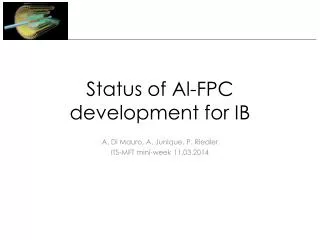
Status of Al-FPC development for IB. A. Di Mauro, A. Junique, P. Riedler ITS-MFT mini-week 11.03.2014. Updated layout . Changes wrt TDR version: Polyimide thickness -> 75 m m ~ 90 W diff. impedance (estimated using Apical NP dielectric constant)

E N D
Status of Al-FPC development for IB A. Di Mauro, A. Junique, P. Riedler ITS-MFT mini-week 11.03.2014
Updated layout • Changes wrt TDR version: • Polyimide thickness -> 75 mm • ~ 90 W diff. impedance (estimated using Apical NP dielectric constant) • Deeper holes (150 mm) better for laser soldering • Larger holes 220 mm, better for laser soldering • Solder mask coverlay, applied by spraying, all gaps are filled avoiding air bubbles formation (observed in PI coverlays). 4 mm 3.5 mm 100 µm 100 µm ~ 10 µm SOLDER MASK AVDD DVDD 25 µm ALUMINIUM 75 µm POLYIMIDE 25 µm ALUMINIUM AGND DGND ~ 10 µm SOLDER MASK 4 mm 11 mm AVDD AGND DVDD DGND ITS-MFT mini-week - Al-FPC - A. Di Mauro
Extension for connection to service cables to be determined 2 1 15 mm 1 High-speed differential lines UEC5 connector (contacts layout not yet implemented) MLVDS differential lines Signals connections
Al-FPC on service cable
Extension for connection to services 2 Flex extension AVDD DVDD 15 mm Power connections Solder connections AVDD & DVDD AGND & DGND
EoC raw and FPC width FPC pad Differential lines 0.2 0.55 (distance of EoC pad axis to chip edge) 0.1 0.1 0.1 0.1 chip edge 1.25 0.2 common distribution of DCTRL and DCLK 0.1 0.1 0.1 0.7 (FPC extra width) 0.15 FPC edge OK for integration! ITS-MFT mini-week - Al-FPC - A. Di Mauro
Al-FPC production procedure Main steps of procedure developed at CERN for STAR flex production (@ LERMPS (F)) : 1) Preparation of polyimide (Apical NP) substrate: • Thermal cycle (12 h at 180 oC) to induce max shrinking (new, under test) • Holes drilling by laser • Sand-blasting + outgassing 2) Deposition of Al layer (25 mm) (performed by DEPHIS (F), FHR (DE)): • Plasma cleaning • Pump down to 10-5 mbar • Cr film coating • Al sputtering (~ 10 h, in several steps to avoid overheating) 3) Chemical etching@ CERN (Laser etching tests by Swiss Micro Laser) 4) Coverlay(solder mask) + Ni/Au @CERN ITS-MFT mini-week - Al-FPC - A. Di Mauro
Summary of production tests ITS-MFT mini-week - Al-FPC - A. Di Mauro
FHR samples #1 ITS-MFT mini-week - Al-FPC - A. Di Mauro
Summary of production tests ITS-MFT mini-week - Al-FPC - A. Di Mauro
DEPHIS samples After etching, w/o coverlay with coverlay ITS-MFT mini-week - Al-FPC - A. Di Mauro
Summary of production tests ITS-MFT mini-week - Al-FPC - A. Di Mauro
FHR samples #2 After Ni/Au: easy peel-off of Al, impossible to use for FPC pads ! reaction to zincate ITS-MFT mini-week - Al-FPC - A. Di Mauro
Summary of production tests ITS-MFT mini-week - Al-FPC - A. Di Mauro
Laser etching tests Using sample from FHR (not compatible with chemical etching!) IR laser UV laser Traces section not yet optimal (trapezoidal), further tests ongoing ITS-MFT mini-week - Al-FPC - A. Di Mauro
Metrology checks • Polyimide shrinking on first exposure to high T: APICAL NP -> 0.04% @150 oC for 0.5 h, 0.08% @ 200 oCfor 2 h • Al-FPC production requires various thermal cycles: • Outgassing: 180 oC • Al sputtering : 90-130 oC • Image transfer: 80 oC • Solder mask: 180 oC • Metrology check to measure induced “shrinking”: distance between first and last contact along trace lines (nominal 268.8) ITS-MFT mini-week - Al-FPC - A. Di Mauro
Metrology checks • avgshrinking = 0.49 (~ 0.2 %) (should be corrected by initial thermal stabilization process) • st. dev. = 0.07 (statistics too small) ITS-MFT mini-week - Al-FPC - A. Di Mauro
Eye diagram • FPC in Cu, 50 mm polyimide ~ 90 W impedance (similar to Al FPC with 75 mm polyimide) • 1.5 Gbit/s (by M. Keil and A. Junique) ITS-MFT mini-week - Al-FPC - A. Di Mauro
Next steps • Validation of chemical etching on LERMPS and DEPHIS FPCs, 6 + 15 prototypes in production • Systematic dimensional control of FPC on all new production from DEPHIS, validate thermal stabilisation; if needed, try compensation of shrinking by modified hole positions in layout • Finalize tests with laser etching and get a quotation from Swiss Micro Laser • Launch pre-series production for IB full prototype ITS-MFT mini-week - Al-FPC - A. Di Mauro