Router Design and Packet Scheduling
760 likes | 937 Views
Router Design and Packet Scheduling. . . . . . . IP Router. A router consists A set of input interfaces at which packets arrive A se of output interfaces from which packets depart Router implements two main functions Forward packet to corresponding output interface Manage congestion.

Router Design and Packet Scheduling
E N D
Presentation Transcript
. . . . . . IP Router • A router consists • A set of input interfaces at which packets arrive • A se of output interfaces from which packets depart • Router implements two main functions • Forward packet to corresponding output interface • Manage congestion
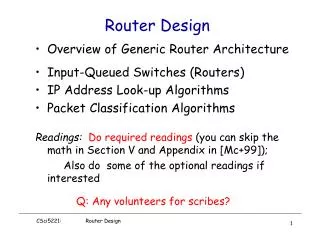
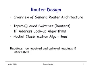
Generic Router Architecture • Input and output interfaces are connected through a backplane • A backplane can be implemented by • Shared memory • Low capacity routers (e.g., PC-based routers) • Shared bus • Medium capacity routers • Point-to-point (switched) bus • High capacity routers inputinterface output interface Inter- connection Medium (Backplane)
What a Router Looks Like Cisco GSR 12416 Juniper M160 19” 19” Capacity: 80Gb/sPower: 2.6kW Capacity: 160Gb/sPower: 4.2kW 6ft 3ft 2ft 2.5ft
POP3 POP2 POP1 D POP4 A B E POP5 POP6 C POP7 POP8 F Points of Presence (POPs)
Basic Architectural Componentsof an IP Router Routing Protocols Control Plane Routing Table Datapath per-packet processing Forwarding Table Switching
Per-packet processing in an IP Router 1. Accept packet arriving on an ingress line. 2. Lookup packet destination address in the forwarding table, to identify outgoing interface(s). 3. Manipulate packet header: e.g., decrement TTL, update header checksum. 4. Send packet to outgoing interface(s). 5. Queue until line is free. 6. Transmit packet onto outgoing line.
Data Hdr Data Hdr IP Address Next Hop Address Table Buffer Memory ~1M prefixes Off-chip DRAM ~1M packets Off-chip DRAM Generic Router Architecture Header Processing Lookup IP Address Update Header Queue Packet
Header Processing Header Processing Header Processing Lookup IP Address Lookup IP Address Lookup IP Address Update Header Update Header Update Header Address Table Address Table Address Table Generic Router Architecture Buffer Manager Buffer Memory Buffer Manager Buffer Memory Buffer Manager Buffer Memory
Packet processing is getting harder CPU Instructions per minimum length packet since 1996
Speedup • C – input/output link capacity • RI – maximum rate at which an input interface can send data into backplane • RO – maximum rate at which an output can read data from backplane • B – maximum aggregate backplane transfer rate • Back-plane speedup: B/C • Input speedup: RI/C • Output speedup: RO/C input interface output interface Inter- connection Medium (Backplane) C RI RO B C
Function division • Input interfaces: • Must perform packet forwarding – need to know to which output interface to send packets • May enqueue packets and perform scheduling • Output interfaces: • May enqueue packets and perform scheduling input interface output interface Inter- connection Medium (Backplane) C RI RO B C
Three Router Architectures • Output queued • Input queued • Combined Input-Output queued
Output Queued (OQ) Routers • Only output interfaces store packets • Advantages • Easy to design algorithms: only one congestion point • Disadvantages • Requires an output speedup of N, where N is the number of interfaces not feasible input interface output interface Backplane RO C
Input Queueing (IQ) Routers • Only input interfaces store packets • Advantages • Easy to built • Store packets at inputs if contention at outputs • Relatively easy to design algorithms • Only one congestion point, but not output… • need to implement backpressure • Disadvantages • Hard to achieve utilization 1 (due to output contention, head-of-line blocking) • However, theoretical and simulation results show that for realistic traffic an input/output speedup of 2 is enough to achieve utilizations close to 1 input interface output interface Backplane RO C
Combined Input-Output Queueing (CIOQ) Routers • Both input and output interfaces store packets • Advantages • Easy to built • Utilization 1 can be achieved with limited input/output speedup (<= 2) • Disadvantages • Harder to design algorithms • Two congestion points • Need to design flow control • Note: recent results show that with a input/output speedup of 2, a CIOQ can emulate any work-conserving OQ [G+98,SZ98] input interface output interface Backplane RO C
Generic Architecture of a High Speed Router Today • Combined Input-Output Queued Architecture • Input/output speedup <= 2 • Input interface • Perform packet forwarding (and classification) • Output interface • Perform packet (classification and) scheduling • Backplane • Point-to-point (switched) bus; speedup N • Schedule packet transfer from input to output
Backplane • Point-to-point switch allows to simultaneously transfer a packet between any two disjoint pairs of input-output interfaces • Goal: come-up with a schedule that • Meet flow QoS requirements • Maximize router throughput • Challenges: • Address head-of-line blocking at inputs • Resolve input/output speedups contention • Avoid packet dropping at output if possible • Note: packets are fragmented in fix sized cells (why?) at inputs and reassembled at outputs • In Partridge et al, a cell is 64 B (what are the trade-offs?)
Cannot be transferred because is blocked by red cell Cannot be transferred because output buffer full Head-of-line Blocking • The cell at the head of an input queue cannot be transferred, thus blocking the following cells Input 1 Output 1 Input 2 Output 2 Input 3 Output 3
Solution to Avoid Head-of-line Blocking • Maintain at each input N virtual queues, i.e., one per output Input 1 Output 1 Output 2 Input 2 Output 3 Input 3
Cell transfer • Schedule: • Ideally: find the maximum number of input-output pairs such that: • Resolve input/output contentions • Avoid packet drops at outputs • Packets meet their time constraints (e.g., deadlines), if any • Example • Assign cell preferences at inputs, e.g., their position in the input queue • Assign cell preferences at outputs, e.g., based on packet deadlines, or the order in which cells would depart in a OQ router • Match inputs and outputs based on their preferences • Problem: • Achieving a high quality matching complex, i.e., hard to do in constant time
A Case Study[Partridge et al ’98] • Goal: show that routers can keep pace with improvements of transmission link bandwidths • Architecture • A CIOQ router • 15 (input/output) line cards: C = 2.4 Gbps • Each input card can handle up to 16 (input/output) interfaces • Separate forward engines (FEs) to perform routing • Backplane: Point-to-point (switched) bus, capacity B = 50 Gbps (32 MPPS) • B/C = 20, but 25% of B lost to overhead (control) traffic
packet header Router Architecture
Update routing tables Router Architecture input interface output interfaces 1 Backplane Data out 15 Data in Set scheduling (QoS) state forward engines Network processor Control data (e.g., routing)
Router Architecture: Data Plane • Line cards • Input processing: can handle input links up to 2.4 Gbps (3.3 Gbps including overhead) • Output processing: use a 52 MHz FPGA; implements QoS • Forward engine: • 415-MHz DEC Alpha 21164 processor, three level cache to store recent routes • Up to 12,000 routes in second level cache (96 kB); ~ 95% hit rate • Entire routing table in tertiary cache (16 MB divided in two banks)
Router Architecture: Control Plane • Network processor: 233-MHz 21064 Alpha running NetBSD 1.1 • Update routing • Manage link status • Implement reservation • Backplane Allocator: implemented by an FPGA • Schedule transfers between input/output interfaces
Data Plane Details: Checksum • Takes too much time to verify checksum • Increases forwarding time by 21% • Take an optimistic approach: just incrementally update it • Safe operation: if checksum was correct it remains correct • If checksum bad, it will be anyway caught by end-host • Note: IPv6 does not include a header checksum anyway!
Data Plane Details: Slow Path Processing • Headers whose destination misses in the cache • Headers with errors • Headers with IP options • Datagrams that require fragmentation • Multicast datagrams • Requires multicast routing which is based on source address and inbound link as well • Requires multiple copies of header to be sent to different line cards
Control Plane: Backplane Allocator • Time divided in epochs • An epoch consists of 16 ticks of data clock (8 allocation clocks) • Transfer unit: 64 B (8 data click ticks) • During one epoch, up to 15 simultaneous transfers in an epoch • One transfer: two transfer units (128 B of data + 176 auxiliary bits) • Minimum of 4 epochs to schedule and complete a transfer but scheduling is pipelined. • Source card signals that it has data to send to the destination card • Switch allocator schedules transfer • Source and destination cards are notified and told to configure themselves • Transfer takes place • Flow control through inhibit pins
The Switch Allocator Card • Takes connection requests from function cards • Takes inhibit requests from destination cards • Computes a transfer configuration for each epoch • 15X15 = 225 possible pairings with 15! Patterns
The Switch Allocator • Disadvantages of the simple allocator • Unfair: there is a preference for low-numbered sources • Requires evaluating 225 positions per epoch, which is too fast for an FPGA • Solution to unfairness problem: Random shuffling of sources and destinations • Solution to timing problem: Parallel evaluation of multiple locations • Priority to requests from forwarding engines over line cards to avoid header contention on line cards
Summary: Design Decisions (Innovations) • Each FE has a complete set of the routing tables • A switched fabric is used instead of the traditional shared bus • FEs are on boards distinct from the line cards • Use of an abstract link layer header • Include QoS processing in the router
Packet Scheduling • Decide when and what packet to send on output link • Usually implemented at output interface flow 1 Classifier flow 2 Scheduler 1 2 flow n Buffer management
Why Packet Scheduling? • Can provide per flow or per aggregate protection • Can provide absolute and relative differentiation in terms of • Delay • Bandwidth • Loss
Fair Queueing • In a fluid flow system it reduces to bit-by-bit round robin among flows • Each flow receives min(ri, f) , where • ri– flow arrival rate • f – link fair rate (see next slide) • Weighted Fair Queueing (WFQ) – associate a weight with each flow [Demers, Keshav & Shenker ’89] • In a fluid flow system it reduces to bit-by-bit round robin • WFQ in a fluid flow system Generalized Processor Sharing (GPS) [Parekh & Gallager ’92]
Fair Rate Computation • If link congested, compute f such that f = 4: min(8, 4) = 4 min(6, 4) = 4 min(2, 4) = 2 8 10 4 6 4 2 2
Fair Rate Computation in GPS • Associate a weight wiwith each flow i • If link congested, compute f such that f = 2: min(8, 2*3) = 6 min(6, 2*1) = 2 min(2, 2*1) = 2 8 (w1 = 3) 10 4 6 (w2 = 1) 4 2 2 (w3 = 1)
Generalized Processor Sharing link • Red session has packets backlogged between time 0 and 10 • Other sessions have packets continuously backlogged flows 5 1 1 1 1 1 0 2 4 6 8 10 15
Generalized Processor Sharing • A work conserving GPS is defined as • where • wi – weight of flow i • Wi(t1, t2) – total service received by flow i during [t1, t2) • W(t1, t2) – total service allocated to al flows during [t1, t2) • B(t) – number of flows backlogged
Properties of GPS • End-to-end delay bounds for guaranteed service [Parekh and Gallager ‘93] • Fair allocation of bandwidth for best effort service [Demers et al. ‘89, Parekh and Gallager ‘92] • Work-conserving for high link utilization
Packet vs. Fluid System • GPS is defined in an idealized fluid flow model • Multiple queues can be serviced simultaneously • Real system are packet systems • One queue is served at any given time • Packet transmission cannot be preempted • Goal • Define packet algorithms approximating the fluid system • Maintain most of the important properties
Packet Approximation of Fluid System • Standard techniques of approximating fluid GPS • Select packet that finishes first in GPS assuming that there are no future arrivals • Important properties of GPS • Finishing order of packets currently in system independent of future arrivals • Implementation based on virtual time • Assign virtual finish time to each packet upon arrival • Packets served in increasing order of virtual times
Fluid GPS system service order Weighted Fair Queueing select the first packet that finishes in GPS Approximating GPS with WFQ 0 2 4 6 8 10
System Virtual Time • Virtual time (VGPS) – service that backlogged flow with weight = 1 would receive in GPS
Service Allocation in GPS • The service received by flow i during an interval [t1,t2), while it is backlogged is
Virtual Time Implementation of Weighted Fair Queueing • ajk – arrival time of packet k of flow j • Sjk– virtual starting time of packet k of flow j • Fjk– virtual finishing time of packet k of flow j • Ljk– length of packet k of flow j if session j backlogged if session j un-backlogged
Virtual Time Implementation of Weighted Fair Queueing • Need to keep per flow instead of per packet virtual start, finish time only • System virtual time is used to reset a flow’s virtual start time when a flow becomes backlogged again after being idle
System Virtual Time in GPS 1/2 1/8 1/8 1/8 1/8 2*C C 2*C 0 4 8 12 16