P13036 Notification Alert
P13036 Notification Alert. Detailed Design Review Date: February 15, 2013 Meeting Location: 17-1545 Meeting Time: 3:00 – 5:00 pm. Technical Review Agenda P13036: Notification Alert

P13036 Notification Alert
E N D
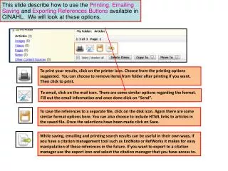
Presentation Transcript
P13036 Notification Alert Detailed Design Review Date: February 15, 2013 Meeting Location: 17-1545 Meeting Time: 3:00 – 5:00 pm
Technical Review Agenda P13036: Notification Alert ------------------------------------------------------------------------------------------------------------------------------------------------------------------------------------------------------------------------------------------------------------------------------------------------------------------------------------------------------------------------------------------------------------------------------ Members Patrick Ganson, CE Stephen Moskal, CE Umer Usman, EE Elizabeth Phillips, EE Thomas Adcock, ME William Johnson, ME Meeting Purpose: 1. Review Traceability Matrix/Risk Assessment 2. Updates on progress for CE and MEs Materials to be Reviewed: 1. Customer Needs/Specifications 2. Risk Assessment 3. Case/Internal Structure Design 4. Thermal Analysis 5. Force Analysis 6. Mobile Application User Interface 7. Software UML Diagram 8. LCD Screen Notification Images 9. Bill of Materials 10. Questions/Concerns
Technical Review Agenda – EE’s P13036: Notification Alert ------------------------------------------------------------------------------------------------------------------------------------------------------------------------------------------------------------------------------------------------------------------------------------------------------------------------------------------------------------------------------------------------------------------------------ Members Patrick Ganson, CE Stephen Moskal, CE Umer Usman, EE Elizabeth Phillips, EE Thomas Adcock, ME William Johnson, ME Meeting Purpose: 1. Provide overview of project history and design methodology 2. Review EE Schematics and Layout Diagram Materials to be Reviewed: 1. Functional Decomposition 2. Customer Needs/Specifications 3. Risk Assessment 4. Case/Internal Structure Design 5. EE Schematics and Diagrams 6. Bluetooth Module Information 7. Bill of Materials
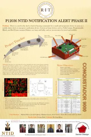
CASE / INTERNAL STRUCTURE DESIGN Dimensions: 132 x 132 x 46 mm ≈ 5.2 x 5.2 x 1.9 in Volume: 801504 mm3 ≈ 48.9 in3 The highlighted area are possible locations for the alert LEDs which will be decided once the location of the PCB is determined.
CASE / INTERNAL STRUCTURE DESIGN This is the top view of the case without the top.
CASE / INTERNAL STRUCTURE DESIGN This is the top view of the case without the top and LCD screen. The highlighted area shows possible locations for the PCB board in the base of the case. Once a final dimension has been established for the PCB the excess space will designed out for our final design.
CASE / INTERNAL STRUCTURE DESIGN Front cut view Side cut view
THERMAL ANALYSIS • Results: • From the Raspberry Pi FAQ page, the components on the Raspberry Pi are rated up to 70°C but not below 0°C. • This means the maximum operation temperature under the worst case conditions is estimated to be 58.8°C, near the ideal value of 60°C listed in the specifications. (The example was 40°C ambient, but the internal temperature is 11.2°C above ambient for any ambient temperature) • Most of the temperature difference is due to the convective thermal resistance on the outside of the case, meaning changes in case thickness for structural reasons will not cause serious detriment to the thermal capabilities of the device. • Overall thermal issues are not expected to be a feasibility concern.
FORCE ANALYSIS • Initial Approach • The initial approach was a simplified model having the case in static loading supporting 20 times the weight of the final device. • Problems with this approach • Static loading does not accurately capture the dynamic aspects that would most likely cause damage to the case or its contents. • The impact in the most damaging configurations is not considered.
FORCE ANALYSIS • Alternate Approaches: • 2D or 3D static analysis at different angles • May require contact elements and several iterations refining the mesh • Will still not give information regarding the harmful dynamic aspects of impact • 2D Dynamic analysis • Will capture some of the dynamic effects needed to properly predict failure • Will be computationally intensive and is beyond material covered in RIT classes such as Advanced Computational Techniques and Computer Implementation of Finite Elements • Will not properly capture the stresses at key points like the enclosure corners • 3D Dynamic analysis • Beyond classes taught at RIT • Speaking with Dr. Boedo of the Mechanical Engineering department, it was suggested that building and testing prototypes would be more effective than trying to complete this analysis
FORCE ANALYSIS • Conclusions and Comments: • The micro-controller case printed earlier in the quarter successfully protected the Raspberry Pi from a drop. • The most reasonable plan at this time it to destructively test prototype enclosures to improve the design. • Alternately the requirement of impact testing may be dropped due to this being a proof of concept which will differ from the final design. • The customer specification is listed as 20G. This amplitude of acceleration falls between a high G maneuver in a fighter plane and what causes harm to humans. • The momentary nature of the impact changes the way in which the case will react. • For example, while normally over 25G will cause death or serious injury, momentary impact in a survivable car crash can reach 100G. This change in the effect of G forces as they act in the short term makes the steady state analysis not very indicative of the actual outcome. • A more useful test may be dropping from a specified height because it is more indicative of what is being tested and requires less instrumentation.
MOBILE APPLICATION USER INTERFACE Main Screen Alarm Screen / Drop Down Menu
MOBILE APPLICATION USER INTERFACE Add Alarm Screen Set Alarms Screen
MOBILE APPLICATION USER INTERFACE App Settings Screen Bluetooth Devices Screen
LCD IMAGES (someone give me a better title) Main Display Screen Email Notification Screen *LED Activation* Alarm Screen *LED Activation* Demonstration following presentation
BATTERY LIFE 10 ½ hours 16 ½ hours Simulation used a 10 Ω resistor to represent the Raspberry PI, causing an average current of 500 mA. The 7.4 V Battery was not completely drained before the test was over due to the 5V regulator being unable to put out the 5V anymore. This is due to the 0.6-0.8 V drop across the MAXIM board and the regulators limitations.
CALCULATIONS • From battery testing, when the battery reaches 6.63V, the 5V regulator can no longer keep the output to sustain the RPi. To avoid this problem, created an indicator circuit to warn customers to plug in. • Choose VBATT to 6.8 V which would give a customer about 30 mins before power would go off in the device. • LM339 Quad Comparator • If IN+ > IN- then output is on • If IN- > IN+, then output floats • Decided to use a voltage divider on the input of the battery to limit voltage and protect the LM339. Choose to use a 10kΩ voltage divider. • In general, VOUT = ½ VIN. To use the LM339, need to use a voltage divider on the input of the 5V to equal 3.4 V. Assume R3 = 10kΩ.
CALCULATIONS MAXIM - MAX1758 Battery Charging Current • The MAX1758 Li-Ion battery charger comes with the ability to configure the current to the battery and input current. For our case, 1A battery charging current will be calculated and the input current will kept at the maximum. Using R4 = 100k Ω and ICHG = 1A
Bluetooth Module After the long discussions, we have chosen to use the BlueGiga WT12 Class 2 Module • Objectives: • Implementation of OPP profile with Android devices • Programming of WT12 using iWrap 5.0 • Use of TXD and RXD links for the Raspberry Pi using UART • Design PCB for WT12 with Android implementation • PCB space for ACP once design has been finalized • Support the future team with WT12 use
The End! • Questions? Comments?