Review Visual System Modeling Tools
210 likes | 385 Views
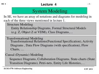
Review Visual System Modeling Tools. Todd Bacastow Penn State University Geospatial System Analysis & Design. Representing System Architecture. Logical View. Implementation View. Use Case View. Process View. Deployment View. Physical. Conceptual. State Diagrams. State Diagrams.

Review Visual System Modeling Tools
E N D
Presentation Transcript
ReviewVisual System ModelingTools Todd BacastowPenn State UniversityGeospatial System Analysis & Design
Representing System Architecture Logical View Implementation View Use Case View Process View Deployment View Physical Conceptual
State Diagrams State Diagrams Class Diagrams Use Case Diagrams Use Case Diagrams State Diagrams Use Case Diagrams State Diagrams Use Case Diagrams Object Diagrams Use Case Diagrams Sequence Diagrams Scenario Diagrams State Diagrams Scenario Diagrams State Diagrams Component Diagrams Collaboration Diagrams Models Component Diagrams Scenario Diagrams Component Diagrams Scenario Diagrams Deployment Diagrams Statechart Diagrams Activity Diagrams Relationship Between Models and Diagrams
Use Cases • Describe interactions between users and computer systems (both called actors) . • Capture user-visible functions. • Achieve discrete measurable goals. • Are typically used during Analysis and Design.
Use Cases Your System Use Case Use Case Actor A Actor A Actor B Actor C Use Case Use Case Use Case Use case disgrams (UML) Use case diagram Use case list Expended use case Data Interface Application
Use Case Diagram Use Case Actor Identify Movie Open Account Customer Clerk Return Movie Review In-Store Telephone Account Status Customer Customer
Use Case Report • The Use Case Report provides documentation for the Use Case. • A Use Case is not complete without the report. • The elements of the Use Case Report are shown on the right. • Brief description • Precondition • Flow of events • Main flow • Subflows • Alternate flows • Postcondition • Special Requirements • Enclosures • Diagrams • Pictures of the UI
Class Diagrams • Are the most fundamental UML Diagram. • Describe the classes in the system, and the static relationships between classes. • Class diagrams are used during Analysis, Design and Development.
UML Class Diagram Customer 1 Rental Invoice 1..* Rental Item 1 0..1 1 Checkout Screen DVD Movie VHS Movie Video Game
UML Class Diagram Multiplicity Customer Simple Aggregation 1 Class Abstract Class Rental Invoice 1..* Rental Item {abstract} 1 0..1 Composition (Dependency) Simple Association Generalization Checkout Screen DVD Movie VHS Movie Video Game
MyClassName +SomePublicAttribute : SomeType -SomePrivateAttribute : SomeType #SomeProtectedAttribute : SomeType +ClassMethodOne() +ClassMethodTwo() Responsibilities -- can optionally be described here. Parts of a Class • Classes can have four parts • Name • Attributes • Operations • Responsibilities • Classes can show visibility and types. • All parts but the Name are optional.
Collaboration Diagrams • Collaboration diagrams describe interactions and links • Focus on exchange of messages between objects • Appears during Analysis phase • Enhanced during Design phase
Collaboration Diagram :Rented Items Object 5: add(customer, movies) 1: enter_customer() 8: generateRentalTotal() 3: enter_movies() 2: IsValidCust(CustId) 7: print invoice() :Check-out Manager :Customer :Clerk 4:GetMovieByBarcode() :Inventory Message
Sequence Diagrams • Can be “morphed” from Collaboration Diagrams. • Describe interactions between objects arranged in time sequence • Focus on objects and classes involved in the scenario and the sequence of messages exchanged • Associated with use cases • Used heavily during Analysis phase and are enhanced and refined during Design phase
Sequence Diagram :CheckoutMgr Cust:Customer :Inventory :RentedItems :Employee 1: find customer() 2: search (string) Object 3: enter movie() 4: search (string) Activation Message 5: rent (movie) 6: add(Cust, item) Lifeline 7: printInvoice() 8: generateRentalTotal()
Component Diagram Component Interface Dependency Note
Deployment Diagram Node Communication Association
Activity Diagram Start State Identify Caller Action State Obtain Name & Address Decision Open Account? Current Customer? [no] [no] [yes] [yes] End State Create Account
Swimlanes and Fork/Join Points Customer Manager Walking Clerk Identify Movie Fork Point Place Order Place Order Fill Order Pay Collect Money Pickup Movie Deliver Movie Join Point
State Diagram Guard Event Transition Action Activity State