Download
1 / 82
870 likes | 1.19k Views
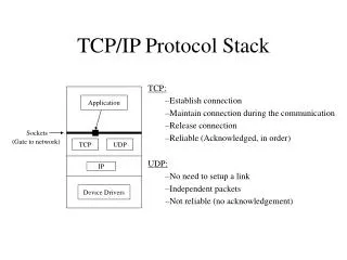
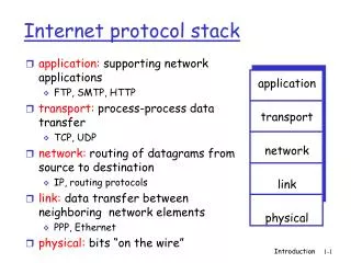
Application: supporting network applications FTP, SMTP, HTTP Transport: data transfer between processes TCP, UDP Network: routing of datagrams from source to destination IP, routing protocols Link: data transfer between neighboring network elements Ethernet, WiFi

E N D
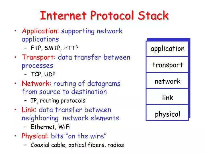
Application: supporting network applications FTP, SMTP, HTTP Transport: data transfer between processes TCP, UDP Network: routing of datagrams from source to destination IP, routing protocols Link: data transfer between neighboring network elements Ethernet, WiFi Physical: bits “on the wire” Coaxial cable, optical fibers, radios application transport network link physical Internet Protocol Stack
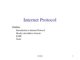
Outline • Introduction to MAC layer • Introduction to IEEE 802.11 • 802.11 Physical layer • 802.11 MAC layer • 802.11 Management
Link Layer Services • Framing, link access: • encapsulate datagram into frame, adding header, trailer • implement channel access if shared medium (e.g., Ethernet) • ‘physical addresses’ used in frame headers to identify source, dest • different from IP address! • coordinate access to a shared medium • reliable delivery between two physically connected devices • flow control • error detection/correction
Multiple Access Protocols • Determine how stations share channel • single shared communication channel • two or more simultaneous transmissions by nodes: interference • only one node can send successfully at a time • What to look for in MAC protocols • Synchronous vs. asynchoronous • Centralized vs. decentralized • Performance: efficiency and fairness
MAC Protocols: a taxonomy • Channel Partitioning • divide channel into smaller “pieces” (time slots, frequency, code) • allocate piece to node for exclusive use • Examples • TDMA: partition time slots • FDMA: partition frequency • CDMA: partition code • Random Access • allow collisions • “recover” from collisions • “Taking turns” • nodes take turns, but nodes with more to send can take longer turns
Random Access Protocols • When a node has a packet to send • transmit at full channel data rate R. • no a priori coordination among nodes • two or more transmitting nodes -> “collision” • random access MAC protocol specifies: • how to detect collisions • how to recover from collisions (e.g., via delayed retransmissions) • Examples of random access MAC protocols: • Pure ALOHA • Slotted ALOHA • CSMA and CSMA/CD
Pure ALOHA • Transmit whenever a message is ready • Retransmit when there is a collision
Slotted Aloha • time is divided into equal size slots (= pkt trans. time) • node with new arriving pkt: transmit at beginning of next slot • if collision: retransmit pkt in future slots with probability p, until successful. Success (S), Collision (C), Empty (E) slots
Problems with Pure/Slotted ALOHA • Pure ALOHA • Transmit whenever a message is ready • Retransmit when there is a collision • Slotted ALOHA • Time is divided into equal time slots • Transmit only at the beginning of a time slot • Avoid partial collisions • Increase delay, and require synchronization Problem: do not listen to the channel.
CSMA: Carrier Sense Multiple Access CSMA: listen before transmit: • If channel sensed idle: transmit entire pkt • If channel sensed busy, defer transmission • Persistent CSMA: retry immediately with probability p when channel becomes idle (may cause instability) • Non-persistent CSMA: retry after random interval
CSMA collisions spatial layout of nodes along Ethernet collisions can occur: propagation delay means two nodes may not hear each other’s transmission collision: entire packet transmission time wasted note: role of distance and propagation delay in determining collision prob.
CSMA/CD (Collision Detection) CSMA/CD: carrier sensing, deferral as in CSMA • collisions detected within short time • colliding transmissions aborted, reducing channel wastage • persistent or non-persistent retransmission • collision detection: • easy in wired LANs: measure signal strengths, compare transmitted, received signals • Can we do collision detection in wireless networks?
CSMA/CD (Collision Detection) CSMA/CD: carrier sensing, deferral as in CSMA • collisions detected within short time • colliding transmissions aborted, reducing channel wastage • persistent or non-persistent retransmission • collision detection: • easy in wired LANs: measure signal strengths, compare transmitted, received signals • difficult in wireless LANs: • receiver shut off while transmitting • receiver’s channel condition is different from that of the sender
Characteristics of wireless LANs • Advantages • very flexible within the reception area • Ad-hoc networks without previous planning possible • (almost) no wiring difficulties (e.g. historic buildings, firewalls) • more robust against disasters • e.g., earthquakes, fire - or users pulling a plug... • Disadvantages • typically very low bandwidth compared to wired networks (1-10 Mbit/s) due to shared medium • Less reliable
Design Goals for Wireless LANs • global, seamless operation • low power for battery use • no special licenses needed to use the LAN • robust transmission technology • simplified spontaneous cooperation at meetings • easy to use for everyone, simple management • protection of investment in wired networks • security, privacy, safety • transparent to applications and higher layer protocols • location aware if necessary
Infrastructure vs. ad-hoc networks infrastructure network AP: Access Point AP AP wired network AP ad-hoc network
Portal Distribution System 802.11: Infrastructure 802.11 LAN • Station (STA) • terminal with access mechanisms to the wireless medium and radio contact to the access point • Access Point • station integrated into the wireless LAN and the distribution system • Basic Service Set (BSS) • group of stations using the same AP • Portal • bridge to other (wired) networks • Distribution System • interconnection network to form one logical network (EES: Extended Service Set) based on several BSS 802.x LAN STA1 BSS1 Access Point Access Point ESS BSS2 STA2 STA3 802.11 LAN
802.11: Ad hoc mode 802.11 LAN • Direct communication within a limited range • Station (STA):terminal with access mechanisms to the wireless medium • Independent Basic Service Set (IBSS):group of stations using the same network STA1 STA3 IBSS1 STA2 IBSS2 STA5 STA4 802.11 LAN
IEEE standard 802.11 fixed terminal mobile terminal infrastructure network access point application application TCP TCP IP IP LLC LLC LLC 802.11 MAC 802.11 MAC 802.3 MAC 802.3 MAC 802.11 PHY 802.11 PHY 802.3 PHY 802.3 PHY
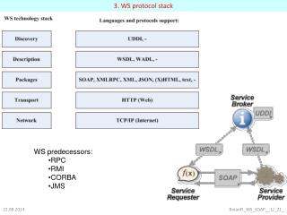
PLCP Physical Layer Convergence Protocol clear channel assessment signal (carrier sense) PMD Physical Medium Dependent modulation, coding PHY Management channel selection, MIB Station Management coordination of all management functions MAC access mechanisms, fragmentation, error control, encryption MAC Management synchronization, roaming, MIB, power management 802.11 - Layers and functions Station Management LLC DLC MAC MAC Management PLCP PHY Management PHY PMD
Outline • Introduction to MAC • Introduction to IEEE 802.11 • 802.11 Physical layer • 802.11 MAC layer • 802.11 Management
Data rate 1, 2, 5.5, 11 Mbit/s, depending on SNR User data rate max. approx. 6 Mbit/s Transmission range 300m outdoor, 30m indoor Max. data rate ~10m indoor Frequency Free 2.4 GHz ISM-band Security Limited, WEP insecure, SSID Availability Many products and vendors Connection set-up time Connectionless/always on Quality of Service Best effort, no guarantees (unless polling is used, limited support in products) Manageability Limited (no automated key distribution, sym. Encryption) Pros Many installed systems and vendors Available worldwide Free ISM-band Cons Heavy interference on ISM-band No service guarantees Relatively low data rate WLAN: IEEE 802.11b
Data rate 6, 9, 12, 18, 24, 36, 48, 54 Mbit/s, depending on SNR User throughput (1500 byte packets): 5.3 (6), 18 (24), 24 (36), 32 (54) 6, 12, 24 Mbit/s mandatory Transmission range 100m outdoor, 10m indoor E.g., 54 Mbit/s up to 5 m, 48 up to 12 m, 36 up to 25 m, 24 up to 30m, 18 up to 40 m, 12 up to 60 m Frequency Free 5.15-5.25, 5.25-5.35, 5.725-5.825 GHz ISM-band Security Limited, WEP insecure, SSID Availability Some products, some vendors Connection set-up time Connectionless/always on Quality of Service Best effort, no guarantees (same as all 802.11 products) Manageability Limited (no automated key distribution, sym. Encryption) Pros Fits into 802.x standards Free ISM-band Available, simple system Uses less crowded 5 GHz band Higher data rates Cons Shorter range WLAN: IEEE 802.11a
Data rate 7.2, 14.4, 21.7, 28.9, …, 72.2 Mbit/s, depending on SNR Multiple input multiple output (MIMO) 20MHz and 40MHz bands Transmission range Increase range by several factors due to MIMO Frequency Free 2.4GHz ISM-band Free 5.15-5.25, 5.25-5.35, 5.725-5.825 GHz ISM-band Security Limited, WEP insecure, SSID Availability Some products, some vendors Connection set-up time Connectionless/always on Quality of Service Best effort, no guarantees (same as all 802.11 products) Manageability Limited (no automated key distribution, sym. Encryption) Pros Fits into 802.x standards Free ISM-band Available, simple system Uses dual band Higher data rates Cons Interference on ISM-band WLAN: IEEE 802.11n
Outline • Introduction to MAC • Introduction to IEEE 802.11 • 802.11 Physical layer • 802.11 MAC layer • 802.11 Management
802.11: MAC layer I - DFWMAC Traffic services • Asynchronous Data Service (mandatory) • exchange of data packets based on “best-effort” • support of broadcast and multicast • Time-Bounded Service (optional) • implemented using PCF (Point Coordination Function) • Broadcast, multicast, and unicast • Uses ACK and retransmission to achieve reliability for unicast frames • No ACK/retransmission for broadcast or multicast frames
802.11 MAC Layer II • Distributed and centralized access methods • DFWMAC-DCF CSMA/CA (mandatory) • collision avoidance via randomized “back-off“ mechanism • minimum distance between consecutive packets • ACK packet for acknowledgements (not for broadcasts) • DFWMAC-DCF w/ RTS/CTS (optional) • Distributed Foundation Wireless MAC • avoids hidden terminal problem • DFWMAC- PCF (optional) • access point polls terminals according to a list
802.11 - MAC layer II • Priorities • defined through different inter frame spaces • no guarantee, hard priorities • SIFS (Short Inter Frame Spacing) • highest priority, for ACK, CTS, polling response • PIFS (PCF IFS) • medium priority, for time-bounded service using PCF • DIFS (DCF, Distributed Coordination Function IFS) • lowest priority, for asynchronous data service DIFS DIFS PIFS SIFS medium busy contention next frame t direct access if medium is free DIFS
IEEE 802.11 DCF • DCF is CSMA/CA protocol • Why not CSMA/CD? • DCF suitable for multi-hop ad hoc networking • Optionally uses RTS-CTS exchange to avoid hidden terminal problem • Any node overhearing a CTS cannot transmit for the duration of the transfer • Uses ACK to provide reliability
CSMA/CA • CSMA/CA: • Wireless MAC protocols often use collision avoidance techniques, in conjunction with a (physical or virtual)carrier sense mechanism • Collision avoidance • Nodes hearing RTS or CTS stay silent for the duration of the corresponding transmission. • Once channel becomes idle, the node waits for a randomly chosen duration before attempting to transmit.
CSMA/CA • Carrier sense • Nodes stay silent when carrier sensed (physical/virtual) • Physical carrier sense • Carrier sense threshold • Virtual carrier sense using Network Allocation Vector (NAV) • NAV is updated based on overheard RTS/CTS/DATA/ACK packets
A B C Hidden Terminal Problem • B can communicate with both A and C • A and C cannot hear each other • Problem • When A transmits to B, C cannot detect the transmission using the carrier sense mechanism • If C transmits, collision will occur at node B • Solution • Hidden sender C needs to defer
A B C Solution for Hidden Terminal Problem: MACA • When A wants to send a packet to B, A first sends a Request-to-Send (RTS)to B • On receiving RTS, B responds by sending Clear-to-Send (CTS), provided that A is able to receive the packet • When C overhears a CTS, it keeps quiet for the duration of the transfer • Transfer duration is included in both RTS and CTS
IEEE 802.11 RTS = Request-to-Send RTS A B C D E F Pretending a circular range
IEEE 802.11 RTS = Request-to-Send RTS A B C D E F NAV = 10 NAV = remaining duration to keep quiet
IEEE 802.11 CTS = Clear-to-Send CTS A B C D E F
IEEE 802.11 CTS = Clear-to-Send CTS A B C D E F NAV = 8
IEEE 802.11 • DATA packet follows CTS. Successful data reception acknowledged using ACK. DATA A B C D E F
Reliability • Wireless links are prone to errors. High packet loss rate detrimental to transport-layer performance. • Mechanisms needed to reduce packet loss rate experienced by upper layers
A B C A Simple Solution to Improve Reliability • When B receives a data packet from A, B sends an Acknowledgement (ACK) to A. • If node A fails to receive an ACK, it will retransmit the packet
IEEE 802.11 RTS = Request-to-Send RTS A B C D E F Pretending a circular range
IEEE 802.11 RTS = Request-to-Send RTS A B C D E F NAV = 10 NAV = remaining duration to keep quiet
IEEE 802.11 CTS = Clear-to-Send CTS A B C D E F
IEEE 802.11 CTS = Clear-to-Send CTS A B C D E F NAV = 8