Twenty Essential Knowledge of Optical Cable
70 likes | 78 Views
An article about basic knowledge of optical fiber cable, including the wavelength, dispersion of optical fiber, insertion loss, return loss, fiber core diameter, types of optical fiber etc. Including What is the mode field diameter (MFD), What is Numerical Aperture (NA), What is the cutoff wavelength and so on.

Twenty Essential Knowledge of Optical Cable
E N D
Presentation Transcript
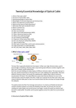
1. What is fiber optic cable? 2. Structure of optical fiber cable 3. Working wavelength of optical fiber 4. Wavelength of minimum dispersion and minimum loss 5. What is the dispersion of optical fiber? 6. What are the causes of fiber attenuation? 7. What does fiber optic bandwidth mean? 8. What is insertion loss 9. What is Return Loss? 10. Fiber core diameter 11. What is the mode field diameter (MFD) 12. What is Numerical Aperture (NA) 13. What is the cutoff wavelength 14. Zero Dispersion Wavelength 15. Dispersion-Shifted optical fibers (DSF) 16. Non-zero dispersion-shifted fiber (NZDF) 17. Types of optical fiber 18. Main types of optical fiber used in optic communications 19. Single mode fibers vs multimode fibers 20. OS1, OS2, OM1, OM2, OM3, OM4, OM5 The bare fiber is generally divided into three layers: 1) fiber core, high refractive index, used to transmit light; 2) Cladding, refractive index is low, forming total reflection condition together with fiber core; 3) Jacket, protect optical fiber. Both the core and cladding are made of glass of different refractive indices. The innermost part is the core, and the second layer on the top of the core is the cladding of an optical fiber. They have different refractive indices, and usually the cladding with a slightly lower index of refraction (usually about 1% lower). This index difference causes total internal reflection to occur at the index boundary along the length of the fiber. A light ray is injected into the fiber optic cable, total internal reflection takes place so that it can transmit down the fiber and does not escape through the sidewalls. The jacket protects the fiber from damage and moisture. It is made up of flexible and abrasion resistant varieties of plastic to increase the flexibility of the fiber. As we know, the core and cladding are made of glass and cannot be bent and fragile. Usually, the jacket has another layer beneath it called buffer. The buffer and the jacket together protect the cable from environmental hazards.
The optical fiber is drawn from pure quartz with a special process into a glass tube thinner than a hair with a few mediums in the middle. Its brittle and brittle texture requires an extra layer of protection. The outer layer of the optical fiber is combined with a plastic protective tube and a plastic sheath to form an optical cable. Broadly speaking, optical fiber is optical cable, but strictly speaking, they are two different products. Optical fiber is a thin, soft medium that transmits light beams. Most optical fibers must be covered by multi-layer protective structure before use, and the covered cables including fibers are called optical cables. Therefore, the optical fiber is the core part of the optical cable, and the optical fiber constitutes the optical cable through the protection of some components and the auxiliary protective layer. Light is defined by its wavelength, and in fiber optic communications, we use light in the infrared region which has wavelengths longer than visible light. In optical fiber communication, the typical wavelength ranges from 800 to 1600nm, and the most commonly used wavelengths are 850nm, 1310nm and 1550nm. Fiber loss and dispersion are two key basic parameters in selecting transmission wavelength to transmit as much data as possible over greater distances. The loss of the single during transmission is attenuation, which is related to the length of wavelength Fiber optic systems usually use the 850, 1310 and 1550 nm wavelengths for transmission because losses are lower at these wavelengths due to properties inherent to the glass. 1550 nm provides lowest loss region, whereas 1310 nm provides lowest dispersion. In the actual application process, the link loss of the 1310nm optical module is generally calculated at 0.35dBm/km, and the link loss of the 1550nm optical module is generally calculated at 0.20dBm/km. Dispersion in an optical fiber is the spreading of light pulses when the wave travels through an optical fiber from an end to another. Light may follow a variety of paths through a fiber optic cable. Each of the paths has a different length, leading to a phenomenon known as dispersion. Dispersion distorts signals and limits the data rate of digital signals sent over fiber optic cable.
Due to different frequencies and modes, dispersion describes the signal distortion as it travels down the fiber. Dispersion in optical fiber includes modal dispersion, chromatic dispersion and polarization mode dispersion. Modal dispersion in optical fibers occurs because different light rays that propagate through a multimode fiber have different propagation delays. So, light shows dispersion due to early reaching and sometimes delay in reaching the other end of the fiber. Chromatic dispersion describes a combination of two separate types of dispersion, namely material dispersion and waveguide dispersion. Material dispersion occurs when the wavelength depends on the refractive index of the fiber core material. The dispersion of optical fiber not only affects the transmission capacity of optical fiber, but also limits the relay distance of optical fiber communication system. The attenuation of the optical fiber is a result of some factors, including absorption, scattering, bending, extrusion, or power loss caused by connectors and fusion splices. It can be calculated in dB (decibels) in terms of voltage. The cable efficiency is high when the attenuation for each unit distance is less. Total attenuation is the sum of all losses. Rayleigh scattering, intrinsic absorption are the inherent losses of optical fibers. There are other factors which could also cause light loss, such as light leakage when fiber is under micro bending, misalignment, uneven end faces during optical fiber docking. Bandwidth refers to the amount of data you can transfer in a unit of time, as well as the range of frequencies used to transmit the data. In a fiber optic network, bandwidth is measured by how many gigabits per second (Gbps) your data can be transferred through the cables. Bandwidth of a fiber is an important factor when designing a fiber optic transmission system. Insertion Loss (usually abbreviated as IL), which mainly refers to the measure of the light lost between two fixed points in the fiber. Insertion loss is measured in decibels (dB). The following equation presents the insertion loss calculation. IL=-10 lg(Pout /Pin), where Pout symbolize the delivered power, Pin is the input power to the system without the passive device. The lower the insertion loss, the better the performance, meaning a value of 0.3dB is preferable to 0.5dB. The recommended maximum dB loss amount for data center fiber optic cabling: LC multi-mode connector: .15dB maximum; LC single mode connector: .15dB maximum; MPO (MTP) multi-mode connector: .20dB maximum; MPO (MTP) single mode connector: .30dB maximum.
Return loss (RL) describes the ratio of reflected light to incident light, which measures the amount of light from the source that is reflected back toward the source. RL=-10 lg(P0/P1), where P1 is the input power to the system, and P0 symbolize the reflected power. Expressed in positive dBs, the higher the value, the better the return loss performance – typical value is -15 to -60dB. According to industry standards: Ultra Physical Contact (UPC): 50dB or higher; Angled Physical Contact (APC): 60dB or higher; Physical Contact (PC): 40dB or higher; typical RL values: 20-40dB. Core size is the physical dimension of the fiber core. Multimode fibers come in a variety of core sizes between 7um and 3mm, of which the most usual are 50um, 62.5um, 100um and 200um. The industry standard for data communications is now 50um and 62.5um multimode using silica glass fibers. The typical core size of single mode is 8.3um. For plastic optical fibers, the fiber core size ranges from 0.25mm to 3mm of which 1mm is the most popular. The Mode Field Diameter describes the distribution of light intensity observed at the cross-section of single-mode optical fiber. MFD is determined by the numerical aperture (NA) and cut-off wavelength of the fiber and is related to the diameter of the fiber core. For transmission fibers, the larger the mode field diameter, the better. In some telecom fibers, the core diameter may be around 9µm while the MFD is about 10.4 µm. For transmission fibers, the larger the mode field diameter, the better. The Numerical Aperture (NA) is a dimensionless number that quantifies the range of angles over which an optical system can accept or emit light. It cannot be directly measured, except in limiting cases with rather large apertures and negligible diffraction effects. It is generally defined as: NA=nsinθ. For 50um multi-mode fiber, the NA is typically of the order of 0.2. And 62.5um multimode fibers typically have a higher NA of 0.28.
Cut-off wavelength is the wavelength above which an optical fiber will allow single mode transmission. In an optical fiber a number of different light-“modes” may exist. Modes are different types of light waves which may each carry different portions of light from the input to the output of the fiber. The wavelength at which the fiber is at the cusp of changing from single-mode to multi-mode is called the Cut-off Wavelength. In a single-mode optical fiber, the wavelength or wavelengths at which material dispersion and waveguide dispersion cancel one another. The zero-dispersion wavelength of single mode fiber is usually around 1310nm. The fiber has a high positive dispersion at an operating wavelength of 1550nm. Both the ITU-suggested G.652 and G.654 fibers are this type. The zero dispersion wavelength is between 1300 and 1324nm, with maximum dispersion D(λ)<3.5 ps/(nm·km) and dispersion slope S. ≤0.093/(nm²·km). Dispersion Shifted Fiber is a type of optical fiber with a core-clad index profile tailored to shift the zero-dispersion wavelength from the natural 1300 nm in silica-glass fibers to the minimum-loss window at 1550 nm. The type of single mode fibers with zero Dispersion near 1550 nm. They are mostly used for dispersion compensation or other kinds of dispersion management in optical fiber communication systems. Non-zero dispersion-shifted fiber (NZDSF), specified in ITU-T G. 655, is a type of single-mode optical fiber which was designed to overcome the problems of dispersion-shifted fiber. This kind of fiber has non-zero dispersion at 1550nm. This Non-Zero Dispersion-Shifted single mode fiber is suitable for high capacity, high data rate metro and long-haul network applications. There are many classification methods to categorize fiber optic cables, such as: Classified by material: LSZH, PVC, HYTREL 7246, HYTREL 7237, PE, TPU According to the outer diameter: φ0.9, φ2.0, φ3.0…… Divided by mode field: single mode (9/125), multimode (50/125, 62.5/125) Divided by color: single mode is yellow, multimode is orange (OM1/OM2), OM3 is aqua blue, OM4 is aqua blue or violet, OM5 is lime green. According to the structure, it can be divided into: generally simplex or duplex, duplex in single-tube, mini multicore, branch cable Optical fiber brands: Corning, YOFC, Fujikura, Sumitomo, OFS, etc.
According to ITU standards, optical fibers are divided into seven types: G651, G652, G653, G654, G655, G656, G657, among which G652 and G657 are commonly used. Multimode fiber G.651 fiber is Multimode graded index fiber Single fiber G.652 is dispersion non-shifted single-mode fiber G.653 is dispersion shifted fiber G.654 is cut-off wavelength shifted fiber G.655 is non-zero dispersion shifted fiber G.656 is low slope non-zero dispersion shift fiber G.657 is bending insensitivity fiber Normally, there are two types of optical fiber: single mode and multi-mode. Single-mode fiber is a single glass fiber strand used to transmit a single mode or ray of light. Single mode fiber with a relatively narrow diameter, through which all signals travel straight down the middle without bouncing off the edges. Single-mode fiber features only one transmission mode. Single Mode Fiber with a relatively narrow diameter of 8.5 to 9.5μm, through which only one mode will propagate typically 1310 or 1550nm. Multi-mode fiber is an optical fiber that allows multiple guided modes to be transmitted. Multi-mode fiber has a larger diameter core, typically 50 or 62.5μm. This larger core allows multiple modes of light to propagate. The standard wavelengths of the multimode are 850 nm and 1300 nm. Multimode fiber is available in four classifications: OM1 (62.5/125 µm), OM2, OM3, OM4 (50/125 µm). There’s also a new multimode fiber standard known as WBMMF (wideband multimode fiber) which uses the wavelengths between 850nm and 953nm.
Both single mode fiber and multimode fiber have a cladding diameter of 125μm. OS1 and OS2 are both single-mode optical fibers. OS1: the ordinary single-mode optical fiber used earlier; OS2: the ordinary optical fiber in use now, the low-water peak optical fiber. In general, OM1 is conventional 62.5/125μm; OM2 is conventional 50/125μm; OM3 is 850nm laser-optimized 50μm core multimode fiber, and in 10Gb/s Ethernet with 850nm VCSEL, the fiber transmission distance can reach 300m; OM4 is an upgraded version of OM3. OM4 multimode fiber optimizes the differential mode delay (DMD) generated by OM3 multimode fiber during high-speed transmission. Therefore, the transmission distance is greatly improved, and the fiber transmission distance can reach 550m; OM5 is a new standard for fiber patch cords defined by TIA and IEC with a fiber diameter of 50/125μm. Compared to OM3 and OM4 fiber patch cords, OM5 fiber patch cords can be used for higher bandwidth applications. The bandwidth and maximum distance are different for different levels of transmission.