Designing a Clock Synchronous Sequential Circuit for Digital Systems: State Assignment Example
Learn how to design a clock synchronous sequential circuit with proper state assignment for digital systems, with guidelines and examples provided. Understand the importance of minimizing state variables and utilizing appropriate encoding techniques.

Designing a Clock Synchronous Sequential Circuit for Digital Systems: State Assignment Example
E N D
Presentation Transcript
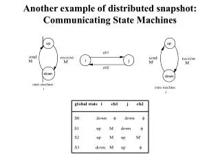
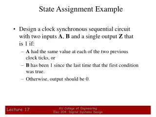
State Assignment Example • Design a clock synchronous sequential circuit with two inputs A, B and a single output Z that is 1 if: • A had the same value at each of the two previous clock ticks, or • B has been 1 since the last time that the first condition was true. • Otherwise, output should be 0. KU College of Engineering Elec 204: Digital Systems Design
State Assignment Example (cont.) A: 0 1 0 0 1 1 1 0 0 1 1 0 1 0 1 1 0 0 B: 0 0 0 0 0 0 0 0 0 0 1 1 1 1 1 0 0 0 Z: 0 0 0 0 1 0 1 1 0 1 0 1 1 1 1 1 1 0 • State definitions: • INIT: initial state • A0: A had 10 but not 00 on the previous clock ticks. • A1: A had 01 but not 11 on the previous clock ticks. • OK0: A had 00, or when OK B=1 and last A=0 • OK1: A had 11, or when OK B=1 and last A=1 KU College of Engineering Elec 204: Digital Systems Design
How to choose the best state assignment? • Formal way: try all assignments! • To much work, not practical. • Guidelines for reasonable state assignments: • Choose an initial state into which the machine can easily be forced at reset (00…0 or 11…1). • Minimize the number of state variables that change on each transition. • Maximize the number of state variables that don’t change in a group of related states. • Exploit symmetries in the problem specifications. • Don’t limit the choice of coded states to the first m n-bit integers. • Decompose the set of state variables into individual bits or fields, where each bit or field has a well-defined meaning wrt the input effects or output behavior. • Consider using more than the minimum number of state variables to make, a decomposed assignment, possible. KU College of Engineering Elec 204: Digital Systems Design
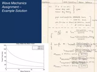
Ex: Decomposed State Assignment • Easy to force reset state • When Q1=1 • Q2 indicates an OK state • Q3 indicates the previous • value of A KU College of Engineering Elec 204: Digital Systems Design
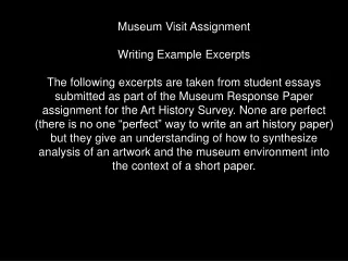
Ex: One-hot State Assignment • One bit to each state • Simple structure • Requires more than • minimum number of • FFs. KU College of Engineering Elec 204: Digital Systems Design
Note on unused states • Minimal Risk: • Consider getting one of the unused (or illegal) states (can be hardware failure, design error, etc). • Identify unused states, create next-state transitions to initial, idle or a safe state. • Minimal Cost: • Assumes the machine never enters to the unused states. • In the next-state table unused states can be marked as don’t cares. • Simplifies excitation logic, but may create problems. KU College of Engineering Elec 204: Digital Systems Design
State Minimization • Should minimize the cost of the final sequential clocked circuit (scct) either by • Reducing the number of gates, or • Reducing the number of FFs • One possible way for this minimization is • Elimination of equivalent states. • Equivalent states: • If it is impossible to distinguish them by observing the current and future outputs of the machine. KU College of Engineering Elec 204: Digital Systems Design
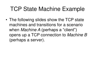
Example on equivalent states: • E G • F D KU College of Engineering Elec 204: Digital Systems Design
Other Flip-Flop Types • J-K and T flip-flops • Behavior • Implementation • Basic descriptors for understanding and using different flip-flop types • Characteristic tables • Characteristic equations • Excitation tables • For actual use, see Reading Supplement - Design and Analysis Using J-K and T Flip-Flops KU College of Engineering Elec 204: Digital Systems Design
J-K Flip-flop • Behavior • Same as S-R flip-flop with J analogous to S and K analogous to R • Except that J = K = 1 is allowed, and • For J = K = 1, the flip-flop changes to the opposite state • As a master-slave, has same “1s catching” behavior as S-R flip-flop • If the master changes to the wrong state, that state will be passed to the slave • E.g., if master falsely set by J = 1, K = 1 cannot reset it during the current clock cycle KU College of Engineering Elec 204: Digital Systems Design
J C K D J K C J-K Flip-flop (continued) • Symbol • Implementation • To avoid 1s catchingbehavior, one solutionused is to use anedge-triggered D asthe core of the flip-flop KU College of Engineering Elec 204: Digital Systems Design
T Flip-flop • Behavior • Has a single input T • For T = 0, no change to state • For T = 1, changes to opposite state • Same as a J-K flip-flop with J = K = T • As a master-slave, has same “1s catching” behavior as J-K flip-flop • Cannot be initialized to a known state using the T input • Reset (asynchronous or synchronous) essential KU College of Engineering Elec 204: Digital Systems Design
T C D T C T Flip-flop (continued) • Symbol • Implementation • To avoid 1s catchingbehavior, one solutionused is to use anedge-triggered D asthe core of the flip-flop KU College of Engineering Elec 204: Digital Systems Design
Basic Flip-Flop Descriptors • Used in analysis • Characteristic table - defines the next state of the flip-flop in terms of flip-flop inputs and current state • Characteristic equation - defines the next state of the flip-flop as a Boolean function of the flip-flop inputs and the current state • Used in design • Excitation table - defines the flip-flop input variable values as function of the current state and next state KU College of Engineering Elec 204: Digital Systems Design
D Q(t 1) Operation + 0 0 Reset 1 1 Set Operation Q(t +1) D 0 0 Reset 1 1 Set D Flip-Flop Descriptors • Characteristic Table • Characteristic Equation Q(t+1) = D • Excitation Table KU College of Engineering Elec 204: Digital Systems Design
T Flip-Flop Descriptors + T Q(t 1) Operation • Characteristic Table • Characteristic Equation Q(t+1) = T Å Q • Excitation Table 0 Q ( t ) No change 1 Q ( t ) Complement + Q(t 1) T Operation Q ( t ) 0 No change Q ( t ) 1 Complement KU College of Engineering Elec 204: Digital Systems Design
Q(t) Q(t+ 1) S R Operation 0 0 0 X No change 0 1 1 0 Set 1 0 0 1 Reset 1 1 X 0 No change S-R Flip-Flop Descriptors S R Q(t + 1) Operation 0 0 Q ( t ) No change • Characteristic Table • Characteristic Equation Q(t+1) = S + R Q, S.R = 0 • Excitation Table 0 1 0 Reset 1 0 1 Set 1 1 ? Undefined KU College of Engineering Elec 204: Digital Systems Design
J K Q(t + 1) Operation 0 0 Q ( t ) No change 0 1 0 Reset 1 0 1 Set 1 1 Complement Q ( t ) J-K Flip-Flop Descriptors • Characteristic Table • Characteristic Equation Q(t+1) = J Q + K Q • Excitation Table + 1) Q(t) Q(t J K Operation 0 0 0 X No change 0 1 1 X Set 1 0 X 1 Reset 1 1 X 0 No Change KU College of Engineering Elec 204: Digital Systems Design
D T C C Flip-flop Behavior Example • Use the characteristic tables to find the output waveforms for the flip-flops shown: Clock D,T QD QT KU College of Engineering Elec 204: Digital Systems Design
S C R J C K Flip-Flop Behavior Example (continued) • Use the characteristic tables to find the output waveforms for the flip-flops shown: Clock S,J R,K QSR ? QJK KU College of Engineering Elec 204: Digital Systems Design