Download
1 / 46
590 likes | 841 Views
Learn about the innovative Ultrasonic Clamp-On Flow Meters by Micronics, designed for accurate flow measurement using TOFD and TT methods. Understand the technology behind transit time measuring and Doppler methods for various operating modes. Ideal for clean and dirty mediums, these meters offer reliable flow measurement for different industries including water treatment, petrochemistry, and energy generation.

E N D
Ultrasonic Clamp-on Flow Meter Ultrasonic Flow Meter Rolf Preikschas
New Ultrasonic Clam-on Flowmeter Portaflow 220 Portaflow 330 Ultraflo 3000/4000 2
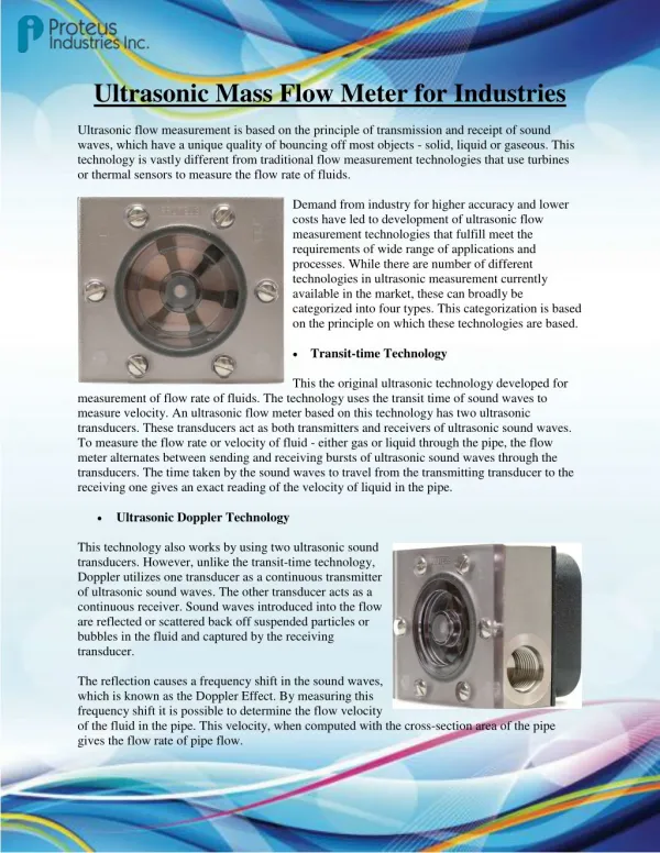
How it works Basically there are two different methods for measuring: TOFD = Time of Flight Diffraction TT = Transit Time --------------------------------------------------------------------------------------------------------- Doppler method --------------------------------------------------------------------------------------------------------- Both ways to measure are base on Echo – Impulse measuring Run-time measuring is used for clean mediums with particles < 3% and particle size of < 100µ Doppler method is generally used for dirty mediums with particles or air bubbles. 4
Sensor Block Sensor Block B A Liquid Flow Pipe wall Transit TimeMeasuring - Theory • When ultrasound is transmitted through a liquid the speed at which the sound travels through the liquid is accelerated slightly if it is transmitted in the same direction as the liquid flow and decelerated slightly if transmitted against it. • The transit time method compares the needed time to transfer the sound from A to B and from B to A. • When the sound properties of the medium and the pipe material are known, is it possible to calculate the flow rate of the transit time difference of the sound. • Is the flow velocity known, the volumetric flow can be calculated for a given pipe diameter. These time difference is very small. A d100 pipe with a velocity of 1m/sec the difference is 30 nanoseconds (30 x 10-9 sec) 5
Transit TimeMeasuring • It‘s possible to measure flowbetween 0.1m/s - 20m/sec. • Optimize the metering window and take the pipe properties (wall thickness, pipe dimension and pipe material) into consideration. • Various metering points guarantee reliable measuring while using low electricity. • The sound signal is received/sent 16 times the average is then calculated. 6
Transit TimeMeasuring - Typical Signal Signal: Copper wire d13, 30l/min 7
Operating Modes Reflex Mode: This is the mode most commonly used. The two transducers are attached to the pipe in line with each other and the signals passing between them are reflectedby the opposite pipe wall. The separation distance is calculated bythe instrument in response to entered dataconcerning the pipe and fluid characteristics. Normally this mode is used for pipes with a diameter of >d32 - d315. Sensor Block Sensor Block B A Liquid Flow Pipe wall 10
Operating Modes Reflex Double- Tripple Mode: These operating modes are used for small (or very small) pipe diameters. Generally we use the double mode. When there’s too weak signal or when it’s a very small diameter we use the tripple mode. The two transducers are attached to the pipe in line with each other and the signals passing between them are bouncing offthe opposite pipe wall (2 or 3 times). The separation distance is calculated bythe instrument in response to entered dataconcerning the pipe and fluid characteristics. Normally this mode is used for pipes with a diameter <d32. Sensor Block Sensor Block B A Sensor Block Sensor Block B A Liquid Flow Pipe wall Liquid Flow Pipe wall 11
Operating Modes Diagonal Mode: This operating mode is used for pipes with big diameter. In this mode the transducers are located on opposite sides of the pip eand the signal will be received without reflection. So it‘s sent/received directly. The separation distance is calculated bythe instrument in response to entered dataconcerning the pipe and fluid characteristics Normally this mode is used for pipes with a diameter of >d315. Sensor Block A Pipe wall Liquid Flow B Sensor Block 12
Clamp-On Flow Meter • Ideal for flow measuring • clean or cleaned medium. • medium with a particle share <3% and a particle size < 100µ • non pulsating flow • fully developed flow profiles • fully filled pipe, no gas pockets Medium • Chemical • Water / pure water • River water • Coolant • Water-Glycol-mixture • Hydraulic oil • Diesel and fuel oil • Heavy oil • Oil manufacture • Food & Beverage Applications • Water Treatment • Water Utilities • Chemical Process Industry • Energy Economy • Energy Generation • Pharma Industry • Semiconductor Industry • Petro chemistry Industry • Food & Beverage 13
General Clamp-On Flow Meter General Data • Bi-directional measuring between -20m/s up to +20m/s • Accuracy: +/-0.5 - 3% of the measured value • Automatic Reynolds compensation • Totalizer for bi-directional Measuring • 10 languages as standard • No Recalibration needed • 4-20mA and pulse output Standard • IP54 resp. IP65 • Battery charger with different plugs 110V – 240V • Display – 64 x 240 Pixel 14
Technical Data PF220- PF330 Portaflow 220 Portaflow 330 15
Data logger PF330 Portaflow 330 16
Technical Data U3000 – U4000 U3000 – U4000 17
Data logger U4000 U4000 18
Transducer Transducer set „A“ As standard for dimension d13 - d115 sound frequency 2MHz Transducer set „B“ As standard for dimension d50 - d2000 - d1000 for PF220 sound frequency 1MHz Transducer set „C“ As option for dimensions d1500 - d5000 sound frequency 0.5MHz Temperature -20ºC till +135ºC Optional HT Transducer set-20ºC till +200ºC The Transducer set must always be used/ changed as a pair. 19
Preparation, Installation in general • Mindinstallation distance • Mind installation angle • Pipes need to be degreased • Remove paint and/or loose rests of paint • Best possible smooth surface • Clean transducer • Apply gel along the middle (ca. 3mm) of the transducer • Do not tighten the transducer too strong 20
Installation 21
Operation • Keypad with dual function keys • numerical data entry • change of flow unit • fast access to menu buttons Enter and scroll Change Flow unit On / Off Quick access to menu buttons 22
Menu Structure • Main menu: • turn on and then press enter • Quick Start • View/ Edit Site Data 20 location possible to save • Data Logger • Setup RS232 / USB • Setup instrument • Read flow 23
Main Menu • Quick start: • Select dimension units: inch or mm • Outside diameter • Pipe wall thickness • Pipe lining thickness • Select pipe wall material • Select pipe lining material (if applicable) • Select fluid type • Enter temperature of liquid • Mechanically set the correct sensor distance • Enter : show flow rate or • Scroll: sensor menu • Sensor-settings: A-ST, B-ST, D • Sensor mode: Reflex, Diagonal, Double-, Tripple Reflex • Temperature of liquid • Exit 24
Main Menu • View Edit Site Data: • You can save up to 20 different sites • Choose from list of sites • Site name • Dimension units: inch or mm • Pipe outside diameter • Pipe wall thickness • Pipe lining thickness • Pipe wall material • Lining material • Sensor set: A-ST, B-ST, D • Sensor mode: Reflex, Diagonal, Double-, Tripple Reflex • Fluid type • Save current site & read flow • Delete this site • Download & save current site • Exit 25
Main Menu • View Logged Data : • Choose from list of sites • View log as text • View log as graphic • Graph Y axis max • Download log • Clear log • Exit 26
Main Menu • Setup RS232 / USB : • Handshaking: Xon/Xoff • Baud rate • Data-Bits • Stop-Bits • Parity • New line • Printer test • Exit 27
Main Menu • Setup Instrument: • Set Date&Time • Calibrate 4-20mA • Pulse Output • Backlight • Factory settings • Change language • Exit 28
Quick access keys • Options: • The menu point “options“ can only be chosen while displaying flow rate • Data review • Zero cut-off: minimum flow • Set zero flow: • Damping: average • Totaliser: On / Off • Reset + Total • Reset - Total • Calibration factor: Multiplication for the display • Roughness factor • Diagnostics: Important for the analysis of the errors • Exit 29
Quick access keys • Logger: • The menu point “logger“ can only be chosen while displaying flow rate • Unit: only display • Log name: only display • Log data to • Logging Interval: 5sec – 1hour • Start Date &Time • Stop Date &Time • Remaining time: only display • Memory rollover: stop or overwriting • Graph Y-axis max • View log as text • View log as graph • Start now • Set auto-start • Clear Log • Select items to log • Extended intervals • Exit 30
Quick access keys • Comms: • The menu point “comms“ can only be chosen while displaying flow rate • Handshaking: Xon/Xoff • Baud rate • Data-Bits • Stop-Bits • Parity • New line • Printer test • Exit 31
Quick access keys • 4-20mA: • The menu point “4-20mA“ can only be chosen while displaying flow rate • mA Output Reading: Only display • Output range: 4-20mA, 0-20mA, 0-16mA • Units: Only display • Flow at max. output • Flow at min. output • Output mA for error • Exit 32
Quick access keys • Pulse: • The menu point “Pulse“ can only be chosen while displaying flow rate • Flow units: Only display • Output: On/Off • Vol(ume) per pulse • Pulse width (ms) • Exit 33
Portograph II • Portograph II is a specially developed software for the ultrasonic clamp on device to observe, save and record the measured data • Automatic communication between the device and PC • Automatic diagram design of data • Data also available in text-form • Change of the metering units and automatic recalculation • Data transfer also to excel • Reverse construction of data which was saved before • Records in real-time • Compatible with Windows data • Help Menu 34
Advantages Clamp-on Technology • No process downtime during installation • Cost savings – No down time • Very easy and economic installation • Cost savings at big dimensions • Adoptable for liquids with different viscosities and densities • Chemical resistant due to no contact with the medium • Ideal also for high purity liquids • Optimal for sterile applications • No limit in pressure range with no pressure loss 40
Other Micronics Equipment Doppler System PF D550 UF D5000 42
Clamp-on Doppler – contaminated medium • If the ultrasonic encounter the moving particle or gas pocket, the system is measuring the complex tone and the frequency change. • The frequency change is proportional to the flow rate, which convert the volume of the flow rate with the inside diameter of the pipe. As a function of the inside diameter of the pipe you can see the flow rate. 43
Other Micronics Equipment Flow rate – metering system for open canals and half filled pipes Stingray AVFM II 44
Other Micronics Equipment Pipe thickness meter 8812 • Pipe thickness of 1.5mm – 200mm • Ultrasonic • 10 different materials • With calibration block 45
Questions? 46