Download
1 / 21
210 likes | 351 Views
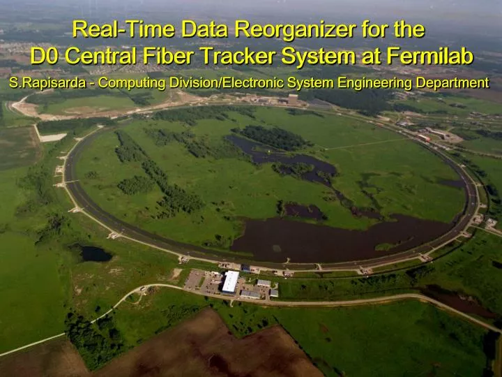
Real-Time Data Reorganizer for the D0 Central Fiber Tracker System at Fermilab. Real-Time Data Reorganizer for the D0 Central Fiber Tracker System at Fermilab. S.Rapisarda - Computing Division/Electronic System Engineering Department.

E N D
Real-Time Data Reorganizer for the D0 Central Fiber Tracker System at Fermilab Real-Time Data Reorganizer for the D0 Central Fiber Tracker System at Fermilab S.Rapisarda - Computing Division/Electronic System Engineering Department S.Rapisarda - Computing Division/Electronic System Engineering Department Real-Time Data Reorganizer for the D0 Central Fiber Tracker System at Fermilab - S. Rapisarda
D0 Experiment D0 Experiment Real-Time Data Reorganizer for the D0 Central Fiber Tracker System at Fermilab - S. Rapisarda
D0 Detector 20 m 66 ft 14 m 46 ft Scintillating Fibers Detector (D0 Central Fiber Tracker) Central Fiber Tracker Electronics Real-Time Data Reorganizer for the D0 Central Fiber Tracker System at Fermilab - S. Rapisarda
Central Fiber Tracker (CFT) Truck convoy carrying CFT to D0 FinishedCFT Inserting CFT into calorimeter bore Real-Time Data Reorganizer for the D0 Central Fiber Tracker System at Fermilab - S. Rapisarda
Optical to Digital Conversion D0 Central Fiber Tracker 40960 scintillating fibers Event frequency 7.6 MHz 40960 clear fibers Visible Light Photon Counters Optical to electrical signal conversion Analog Front-End Boards Analog to digital signal conversion 320 LVDS SERDES 371MHz links Links Throughput: 347 Gigabit/second Data Throughput: 311Gigabit/second Real-Time Data Reorganizer for the D0 Central Fiber Tracker System at Fermilab - S. Rapisarda
Track Recognition D0 Central Fiber Tracker 40960 scintillating fibers Event frequency 7.6 MHz Visible Light Photon Counters Optical to electrical signal conversion Analog Front-End Boards Analog to digital signal conversion 320 LVDS SERDES 371MHz links Digital Front-End Boards Track recognition List of found tracks D0 Trigger Framework Real-Time Data Reorganizer for the D0 Central Fiber Tracker System at Fermilab - S. Rapisarda
Trigger sectors • Fibers from detectors have cylindrical geometry (in blocks of 256) • Track recognition electronics (DFEs) requires data organized in azimuthal (trigger) sectors…. Central Fiber Tracker80 4.5º wide sectors, 512 fibers => 512 bits @ 7.6 MHz5 72º wide Super-Sectors, 8192 fibers => 8192 bits @7.6 MHz Real-Time Data Reorganizer for the D0 Central Fiber Tracker System at Fermilab - S. Rapisarda
The Missing Piece D0 Central Fiber Tracker 40960 scintillating fibers Event frequency 7.6 MHz 40960clear fibers Optical box to reorganize fibers? Visible Light Photon Counters Optical to electrical signal conversion or Analog Front-End Boards Analog to digital signal conversion 320 LVDS SERDES371MHz links Digital box to reorganize data? Digital Front-End Boards Track recognition D0 Trigger Framework Real-Time Data Reorganizer for the D0 Central Fiber Tracker System at Fermilab - S. Rapisarda
Data Mixer System D0 Central Fiber Tracker 40960 scintillating fibers Event frequency 7.6 MHz Visible Light Photon Counters Optical to electrical signal conversion Analog Front-End Boards Analog to digital signal conversion 320 LVDS SERDES371MHz links Data Mixer System Real-time data reorganization 320 LVDS SERDES371MHz links Digital Front-End Boards Track recognition D0 Trigger Framework Real-Time Data Reorganizer for the D0 Central Fiber Tracker System at Fermilab - S. Rapisarda
Mixer System Requirements 1st level of data serialization from 7.5 MHz to 53 MHz 2nd level of serialization (LVDS SERDES) 53MHz to 371MHz Analog Front-End Boards Analog to digital signal conversion Limitations and challenges: • Defined I/O interfaces • High data throughput 311 Gigabit/second • Marginal throughput available on I/O links • Limited space available • Minimal delay (200 nsec ?) • One board design should fit all the system needs • Limited budget & time 320 LVDS SERDES371MHz links Data Mixer System Real-time data reorganization Advantages: • Some degrees of freedom in specifying the 1st level of serialization in the AFEs • Minimal limitations imposed by the DFEs on the 1st level of serialization • Minimal flexibility required for future upgrades/changes • System partitionable in five identical and independent subsytems of four boards each. Each subsystem has to handle the data from one supersector. 320 LVDS SERDES371MHz links Digital Front-End Boards Track recognition Real-Time Data Reorganizer for the D0 Central Fiber Tracker System at Fermilab - S. Rapisarda
Mixer Subsystem Analog Front-End Boards • The fiber detector can be logically partitioned into 5 identical and independent angular sectors. LVDS SERIALIZERS (1/5 of the detector data) 64 LVDS SERDES links Data Mixer Subsystem • The mixer system is partitioned into 5 identical and independent subsystems. DES DES DES DES Board#1 Board#2 Board#3 Board#4 SER SER SER SER 64 LVDS SERDES links Digital Front-End Boards LVDS DESERIALIZERS Real-Time Data Reorganizer for the D0 Central Fiber Tracker System at Fermilab - S. Rapisarda
MS Excel Based Tool • A MS Excel based tool has been implemented and used to: • Operate on data • Visualize data attributes • Compare different board architectures and choose one • Minimize number of chip-to-chip connections • Minimize number of board-to-board connections • Define/assign data mapping for the input links, chip-to-chip connections (FPGAs I/O), board-to-board connections (backplane), output links • After having defined a data multiplexing model, to automatically generate VHDL code for data mixing. Real-Time Data Reorganizer for the D0 Central Fiber Tracker System at Fermilab - S. Rapisarda
MS Excel Based Tool Colors… Mixer board 1 Mixer board 2 Mixer board 3 Mixer board 4 Link# 32 33 1 16 17 48 49 64 Bit# 1 140 Real-Time Data Reorganizer for the D0 Central Fiber Tracker System at Fermilab - S. Rapisarda
Mixer Board Architecture 16 LVDS SERDES 371MHz Links Data Throughput 15.5 Gigabits per second MIL-STD1553 LVDS Receivers BoardControl BACKPLANE SubrackController Data Synchronization Diagnostic BackplaneData TXs/RXs Timingcontrol Data reorganization LVDS Transmitters 16 LVDS SERDES 371MHz Links Data Throughput 15.5 Gigabits per second Real-Time Data Reorganizer for the D0 Central Fiber Tracker System at Fermilab - S. Rapisarda
Mixer Board Layout Real-Time Data Reorganizer for the D0 Central Fiber Tracker System at Fermilab - S. Rapisarda
Configuring Mixer System • One of the 17 FPGAs on the board (board controller) is automatically configured at power-up by an on-board EEPROM. The EEPROM content is modifiable through a front panel JTAG interface port. • The board controller interact with the subrack controller and handles the configuration of the remaining 16 FPGAs. • The FPGAs configuration files are stored on a removable CompactFlash card on the subrack controller. • At power-up the configuration time for the full mixer system is 30 seconds Subrack controller Mixers Real-Time Data Reorganizer for the D0 Central Fiber Tracker System at Fermilab - S. Rapisarda
Diagnostics Remotely accessible throughthe subrack controller Front panel accessto diagnostic • Input links clock error • Input links frame marker error • Input links clock synchronization error • Input links frame synchronization error • Input links control bits detection • Input links test pattern detection • Board local bus • Backplane serial bus • Backplane general-purpose bus • FPGAs configuration status • Output links test pattern transmission • Error latching • Measurement of data frame misalignment • Data frames re-synchronization • Control bits masking • Input and output link shutdown • Timing reference information Real-Time Data Reorganizer for the D0 Central Fiber Tracker System at Fermilab - S. Rapisarda
Testing • Boundary Scan (individual board) • Test-rack (individual subsystems) Subsystem under test Mixer System Test Rack Full system under test before commissioning Real-Time Data Reorganizer for the D0 Central Fiber Tracker System at Fermilab - S. Rapisarda
Data Mixer System D0 Central Fiber Tracker 40960 scintillating fibers Event frequency 7.6 MHz Visible Light Photon Counters Optical to electrical signal conversion Analog Front-End Boards Analog to digital signal conversion 320 LVDS SERDES371MHz links Data Mixer System Real-time data reorganization 320 LVDS SERDES371MHz links Digital Front-End Boards Track recognition D0 Trigger Framework Real-Time Data Reorganizer for the D0 Central Fiber Tracker System at Fermilab - S. Rapisarda
Mixer System D0 Central Fiber Tracker 40960 scintillating fibers Event frequency 7.6 MHz Visible Light Photon Counters Optical to electrical signal conversion Analog Front-End Boards Analog to digital signal conversion 320 LVDS SERDES371MHz links Data Mixer System Real-time data reorganization 320 LVDS SERDES371MHz links Digital Front-End Boards Track recognition D0 Trigger Framework Real-Time Data Reorganizer for the D0 Central Fiber Tracker System at Fermilab - S. Rapisarda
Acknowledgment Thanks to N.G.Wilcer co-designer of the mixer system J. Anderson, R.Angstadt, F. Borcherding, B. Haynes, D. Husby, J.Olsen, J. Smith, and M. Vaz for major contributions to the design of the Mixer system; S. Bledsoe, J. Chramowicz, S. Grünendahl, G. Ginther, S. Lynn, P. Rubinov, and M. Tomoto for their invaluable help in the assembly, debugging, and commissioning of the Mixer system. Contacts: S. Rapisarda, N. Wilcer (email rapisard@fnal.gov, wilcer@fnal.gov)Project website: http://www-ese.fnal.gov/D0_CTT_Mixer/ Real-Time Data Reorganizer for the D0 Central Fiber Tracker System at Fermilab - S. Rapisarda