Download
1 / 21

E N D
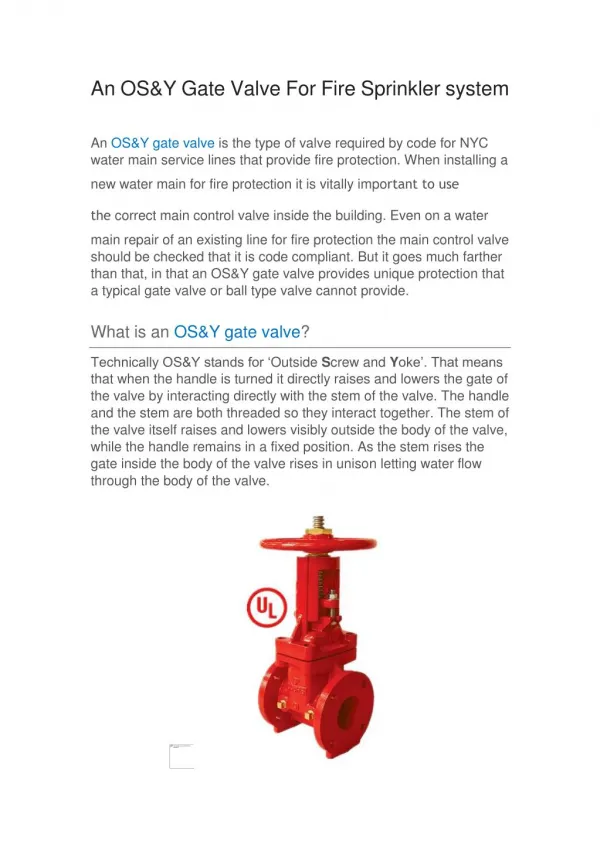
New and advanced technOLOGIEs in Petroleum and Refinery industry Dr. Ilmer Yu. Khasanov – Bashkir State University, Scientific and Production Center “Sherik”, RussiaDespite 170 years history of the oil production which made a revolution in development of human society, here are still "entire strata" of unsolved problems, still remaining to be solved. From whole lot of problems, without graduating them in terms of value, I am going to show some, in my humble opinion, long range tasks in several oil and gas business domains at various levels of engineering design maturity. I would be genuinely glad to open, in cooperation with you, the doors to future for products in below-mentioned and other directions.
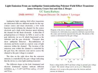
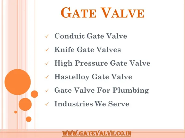
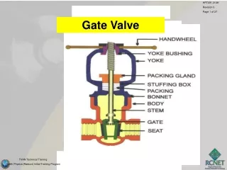
Succesfully have been developed highly reliable gаte valves of ZKSsh type (Quick Acting Sector End Valve) – a new stage in development of equipment for petrochemical industry. • These type of gates are available for both horizontal and vertical application. END GATE VALVE
END GATE VALVE FOR HORIZONTAL “APPARATUSSES “ 1 7 2 3 6 1– flange; 2– cover; 3– sector; 4 – screw; 5 – nut; 6– flywheel; 7 – fulcrum arrangement; 8–safety device; 9 – sealing ring; 10 – packing ring 8
SECTOR END GATE FOR VERTICAL “APPARATUSES” 6 1 5 2 4 1 3 7 2 6 7 1 8 1– flange; 2– cover; 3– sector; 4 – screw; 5 – nut; 6– pivot device; 7 – support; 8 – casing;9 – sealing ring; 10 –cup-type seal
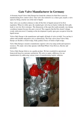
sector end gate photoS End gate valve at the manufacturer plant Sector end gate at cleaning and diagnostics devices launching/receiving chamber
ACHIEVMENTS • Gate included into Gazprom PJSC procurement list • License agreements signed with two manufacturers in the Russian Federation • WORTHWHILE • To implement the gate at all revamped and new installations: • -at oil and gas processing facilities instead of bayonet gates; • - in transportation systems instead of yoke and other type gates; • - at installations of refining and petrochemical companies as well as other branches of industry instead of flange, yoke and other types of gates; • NECESSARY • The sector type gates need: • - improvement of design; • - manufacturing process improvement; • - marketing; • - presentation; • - heavily exploit, using all and any possibilities.
When oil contamination occurs in the first place it is necessary to identify the volume of spilled oil, its inflow in real-time mode. Nowadays one may quite rapidly and precisely identify the area of any spillage but no device exists for the rapid and precise measurement of thickness of oil spilled on the water body surface. Therefore the estimates of spilled oil amount considerably differ. • This task may be solved by the apparatus for rapid measurement of thickness of oil spill on the water surface. Apparatus for rapid measurement of oil spill thickness
metering unit of the apparatus for rapid measurement of thickness of oil spill on the water surface..… 1-3 – cutoffs; 4 – measuring tube; 5 – scale; 6 – tube case; 7 - valve; 8 – evacuator to produce a vacuum.
Thickness of oil layer (slick) is determined on condition of the same volumes of oil in the cutoff and in the calibrated tube, i.e. • Scutoff·δ = Stube ·h • then the thickness of oil slick is • δ = (S pipe/Scutoff)·h • where Stube, Scutoff – cross-section area of tube and cutoff correspondingly; • h – height of oil column in the tube measurement of thickness of oil spill on water body surface
CHALLENGES The device while providing the rapid measurement should be able to:- register date, time, position data of measurement point;- register the height of oil column in the measuring tube;- be fit for simultaneous measuring of thickness and taking of representative sample;- function during sea agitation (up to set values). DEMANDThe device will be useful for both oil spillers as well as for the regulatory agencies and authorities
There are no oil skimmers capable of collecting spilled oil at low ambient temperatures, specifically viscous and high pour point oil. • The overflow type oil skimmers with the wave monitoring oil receivers are most practical in the flowing water and during agitation while the adhesive type oil skimmers are more useful at calm water and in low velocity water flows. the oil skimmers of overflow type collect up to 70% or more of oil-carrying water, the oil skimmers of adhesive type collect oil with 3-5% water content or less. Oil Skimmer
adhesive type oil skimmer Overall view 1- frame, 2 - rotating drums; 3 - oil receiver, 4 & 5 - scrappers system, 6 - trays, 7 - drums drive, 8 - heating fluid supply unit; 8 – manifold; 9 - pumping unit for collected oil with a drive; 10 & 11 - alternating dents and projections; 12 – float. Schematic drawing
We investigated and found solutions for oil gathering drum with a smooth and corrugated, pike-shaped (triangle), П – shaped surfaces [2]. Some results of calculation of the drum with a smooth surface is provided below. • Calculations are done for parameters as follows: ƍ=850 kg/m3, R=0.2 m; Н=0.1 m; g=10 m/s2; ν=10-5 m2/s; ω=3.14 с-1. • Dependence of unit efficiency on the approach velocity VНat different h: 1- 0.001 m; 2– 0.03 m; 3 – 0.05 m; 4 – 0.07 m; 5 – 0.09 m. STUDY RESULTS
STUDY RESULTS (continued) Dependence of oil skimmer efficiency on VНat different ν: 1 – 10-5m2/s; 2 – 1.2·10-5m2/s; 3 – 1.4·10-5m2/s; 4 – 1.6·10-5m2/s; 5 – 1.8·10-5m2/s. Dependence of oil skimmer efficiency on H/R at different VН: 1 – 0.01 m/s; 2 – 0.02m/s; 3 – 0.03m/s; 4 – 0.04m/s; 5 – 0.05m/s.
The key issue during the creation of oil skimmer is the adsorbing capacity of the drum’s material, therefore a comparative assessment of adsorbing capacity of solid materials potentially applicable as drum materials has been done. Study fragments are given in the table. MATERIAL SELECTION FOR SKIMMER DRUM
The choice of material for manufacturing of drum skimmer working surface shall be determined not by the capacity of material “to attract and hold oil on its surface”, but by: • - the drum manufacturability, ability to manufacture a light rigid unit to ensure positive buoyancy and mechanical strength of the whole structure; • - resistance to abrasion from contact with scrappers – oil removers; • - high heat conductivity for heating of external surface and ability of structure to compensate the environment (water, air) temperature changes; • - corrosion resistance to water solutions of salts, sour and highly sour hydrocarbons; • - strength; • - availability and relative low price. The oil skimmer needs modification to improve its weight/overall dimension characteristics as well as design and production process to be ready for mass production and wide distribution Criteria for selecting the drum material
The researches showed that notwithstanding of design the maximum flow velocity is described by the equation (11) • at which the separate flow of phases oil – water is provided and the “diving” effect is absent i.e. the barrier does not pass the floating oil. • Where - gravity acceleration, – static pressure at the depth of bottom edge of oil boom screen; – surface tension at oil – water interface; – oil density. • The problem is resolved by drift oil booms of aero-hydrodynamic principle – similar to the pneumatic barriers which are used it the oil ports – based on creation of air-water hill. / Oil Booms UTILIZING aerohydrodynamics principle
The figure presents the calculation of average height of water-air wave versus air flow rate (U = 0.3m/s; 1·h0=0.4m; 2·h0=0.8m; 3·h0=1.2m). Thus at half-width of bubble generator l =1, length L =10m, height of its submersion h0=1.2m and volume of air supply h=104 m3/h the height of water-air wave at the edge of oil slick shall be ∆h≈30cm. • … DependEnce of water-air wave height from the air flow rate
Vertical view Sectional elevation • 1 – shells; 2 – sections docking unit; 3 – heating medium supply line; 4 – bracing; 5 – hoist;6 – devices for counterweights; 7 – air generator; 8 –containment devices fastening elements; 9 – safety chain;10 – dampener Vertical view Sectional elevation General view of oil boom
1 – oil; 2 – water-air wave; 3 – dampener; 4 – heated shell; 5 – air generator; 6 – service platform; 7 – railing; 8 – roof; 9 – ice surface • If you are interested in our development results we could jointly improve,manufacture and sale them. • I see possibilities for their improvement regarding manufacture procedure, improvingtheir reliability and design. Process functional diagram of aerohydrodynamic principle oil boom