Download
1 / 27
330 likes | 651 Views
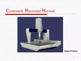
C OORDINATE M EASURING M ACHINE. Zeiss-Prismo. ZEISS Prismo,Spectrum, UMM550, Contura, Vista, Eclipse MITUTOYO Legex, Beyond Crsyta BROWN & SHARPE Global, Scirocco WENZEL MAHR. Zeiss-Vista. CMM PRODUCERS. Mitutoyo-Legex. Brown & Sharpe. CMM Producers. High Accuracy

E N D
COORDINATE MEASURINGMACHINE Zeiss-Prismo
ZEISS Prismo,Spectrum, UMM550, Contura, Vista, Eclipse MITUTOYO Legex, Beyond Crsyta BROWN & SHARPE Global, Scirocco WENZEL MAHR Zeiss-Vista CMM PRODUCERS
Mitutoyo-Legex Brown & Sharpe CMM Producers
High Accuracy Universal and Flexible Versatile in any Workpiece Dimensions Reverse Engineering Reduce Measuring and Setting-up Time Allow Dimensional and Geometrical Simultaneously WHY CMM Zeiss - Vista
BASIC PRINCIPLE OF MEASUREMENT • Measurements are made in a traversing frame with 3 orthogonal axis (X,Y,Z) • Displacement along the axes are read by length measuring system (Phocosin) and transferred to an electronic control cabinet • Function (Phocosin) to take measurement point determined by the probe head & represent it in a Cartesian coordinate system
These systems consist of incremental encoders using a grating scale as a measurement standard. Length-measuring systems (Phocosin)
DESIGN OF CMM • BRIDGE • HORIZONTAL ARM • GANTRY • ARTICULATING ARM Gantry CMM Inspects Huge Auto Stamping Dies
DESIGN OF CMM- Bridge Moving Bridge architecture schematic
DESIGN OF CMM- Bridge Fixed Bridge architecture schematic
DESIGN OF CMM- Gantry Bridge architecture schematic Zeiss – MTC (Gantry)
DESIGN OF CMM- HORIZONTAL ARM Horizontal arm architecture schematic
Probe Head Compressed air unit Min requirement 5 bar X,Y,Z Measuring System (Phocosin) CMM Table – Granite X,Y,Z Motor Air Bearing - 6µm high air slit STRUCTURE OF CMM-UMM550
The travel movements of CMM in all axes are recorded by incremental path measuring systems and store in a counter as position. When a probing is made the measured value of each axis is formed from the position stored and the remaining deflection of the probe system Principle of forming the measured value
Correlation between probe head output, length measuring data, and resulting measurement value ( MC ) : MC = machine coordinate, PH = probe head output The probe head does not have to be in the zero position during probing, as the deflection in a probe head axis is exactly copied in the length measuring system of the corresponding CMM axis The probe head output and the CMM length measurement values are added in all 3 measuring axis. Principle of forming the measured value
SOFTWARE UNIX WINDOWS NT DOS • UMESS-UX • SAM-UX-STAT • KUM-UX-2D/3D CURVES • HOLOS-UX-FREEFORM DIGITISING & • MEASURE • GEAR-UX-SPUR & HELICAL • G-BEVEL-UX-BEVEL GEAR • CALYPSO – • GEOMETRY • CC CURVE • HOLOS - NT SOFTWARE
MEASURING SOFTWARE • UMESS UX Measurement of 2D 2. KUM UX Measurement of 3D Curves Digitizing/Scanning • HOLOS • CALYPSO
TO ACTIVATE UMESS SOFTWARE FUNCTION • Pull down menu • Pictograms/Icons • Direct Input No.
Pull Down Menu-PROBE • CALIBRATION Master Probe (MODE) Measuring Probe (CLAMPED/UNCLAMPED) CLAMPED One axis only free, depending on the probe direction UNCLAMPED All axis are free to move (for 3D profile)
Pull Down Menu-COORD • ALIGNMENT Rotate Space Rotate Plane • ZERO POINT
Pull Down Menu-ELEMENTS • FOR MEASUREMENT OR PROBING Geometric Element –Need to be defined SURFACE LINE CIRCLE CONE CYLINDER SPHERE TORUS ECLIPSE
Pull Down Menu-CMM • TO TRAVEL AT DEFINED POSITION (Auto Movement) • TO TRAVEL AT MACHINE ZERO POINT (Reference Points travel- Eg.X30,Y-30,Z-30)
Pull Down Menu-CNC & EVAL CNC • TO CREATE CNC PROGRAM EVAL • LINKAGE FUNCTION FORM POSITION DISTANCE (Cartesian,Polar,Perpendicular)
Pull Down Menu-EVAL INTERSECTION 1. Line to Line 2. Line to Circle 3. Circle to Circle SYMMETRY ELEMENT DISTANCE
Pull Down Menu-RECORD • TO CREATE TEXT Customer Operation Inspector Product • PRINTER MODE