Download
1 / 25
1.01k likes | 3.04k Views
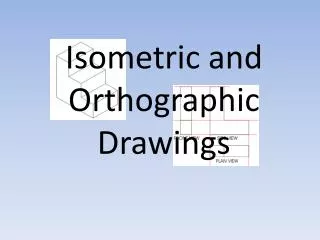
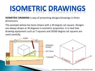
Isometric and Oblique drawings. Isometric drawing. Is based on equal measurements on three lines called Isometric axes: All vertical lines on the original object remain vertical Horizontal lines on the original object are drawn at an angle of 30 o to the horizontal.

E N D
Isometric drawing Is based on equal measurements on three lines called Isometric axes: • All vertical lines on the original object remain vertical • Horizontal lines on the original object are drawn at an angle of 30o to the horizontal
Three methods of using isometric axes: O – start point OA,OB and OC - Isometric axes Reversed isometric. It leads to optical illusion (usually not in use)
True isometric projection • Originally obtained by rotation of a cube through 45o and then tilting it until OB become equal to OA and OC A C O B
In true isometric, measurements in relationship to the orthographic projection are foreshortened to approximately 0.82 • Australian Standard Engineering Drawing Practice recommends that all measurements on the isometric axes be in the proportions of 1:1:1 Standard isometric of a cube 40x40x40 True isometric of a cube 40x40x40
Isometric drawing by envelope method • Produce an isometric drawing of the shown component:
All verticals remain vertical • All horizontals turn at an angle of 30o to the horizontal • All parallel lines remain parallel • All sizes are in the same proportion as in the original object • Angles are formed by plotting the staring and finishing pints on isometric lines
At the end remove all lines that are not part of the drawing
Circles in isometric drawings • When circles are represented in isometric they become ellipses
How to draw the correct ellipse • Divide the circle into a number of ordinates having the same spacings or
Draw isometric axis (30o to horizontal) • Transfer the spacing from the circle to the isometric axis • Transfer the ordinates from the circle to the isometric axis in the same order. • Draw the ellipse passing through the ends of the ordinates
Same procedure can be carried for each isometric axis on each visible plane
Oblique drawings Any angle Oblique axes are defined in the following manner: • All vertical lines of the original object are assumed to remain vertical. • One set of horizontal lines of the original object is assumed to reman horizontal. • The other set of horizontal lines of the original object recede at a convenient angle to the first set of horizontal lines. • Angles of receding planes must be plotted as in isometric drawing
What if we transfer linear measurements in ration 1:1:1 like in isometric? • Let we try with a cube using 45o angle It doesn’t look like a cube!
In order to achieve realistic outlook of the object a reducing scale shall be applied on the linear measurements on the angled axis The scale varies depends on the angle
We are going to make an oblique drawing of a component using similar envelop technique • Do not forget to scale measurements parallel to the angled oblique axes • For this exercise use 45o angle i.e. use the proportion