Download
1 / 14
140 likes | 344 Views
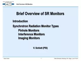
Brief Overview of SR Monitors. Introduction Synchrotron Radiation Monitor Types Pinhole Monitors Interference Monitors Imaging Monitors. V. Schlott (PSI). Synchrotron Radiation Monitors: Transverse Profiles and Emittance.

E N D
Brief Overview of SR Monitors Introduction Synchrotron Radiation Monitor Types Pinhole Monitors Interference Monitors Imaging Monitors V. Schlott (PSI)
Synchrotron Radiation Monitors: Transverse Profiles and Emittance beam emittance: projected area of transverse phase space volume in case of a „flat lattice“ (low coupling) with hy ≈ 0 → horiz. beam size use location with hx = 0 for ex measurement → vertical beam size → beam divergence • b-functions and dispersion are well known in light sources → e can be determined from beam size s • synchrotron radiation from bending magnets (undulators and wigglers) are non-invasive sources • small opening angle Q ~ 1/g (typ. << 1 mrad) of synchrotron radiation limits spatial resolution due to diffraction → spatial resolution limit: for l = 500 nm and DQ = 1 mrad measurement of small beam sizes...: → X-ray pinhole camera → interferometeric techniques (UV, visible radiation) → X-ray (VUV) imaging
Synchrotron Radiation Monitors: X-Ray Pinhole Camera X-ray pinhole camera resolution is limited by: Example from ALBA, U. Iriso et al., EPAC 2006 with L1 = 6 m L2 = 12 m l = 12 nm (17 keV) → w = 20 mm ... blurring ... diffraction typical resolution limitation of x-ray pinhole cameras ~ 10 mm Example: PETRA III Pinhole Camera ESRF ID-25 X-Ray Pinhole Camera Ø 18 μm hole in 500 μm thick Tungsten plate courtesy of K.Scheidt, ESRF courtesy of G. Kube, DESY P.Elleaume, C.Fortgang, C.Penel and E.Tarazona, J.Synchrotron Rad. 2 (1995) , 209
Synchrotron Radiation Monitors: X-Ray Pinhole Array BESSY II X-Ray Pinhole Array W.B. Peatman, K. Holldack, J.Synchrotron Rad. (1998) 5, 639-641 diffraction limited resolution: ~ 11 mm simultaneous measurement of...: → beam size through single pinhole image → beam divergence through envelope
Synchrotron Radiation Monitors: Principle of Interference Monitors a two-beam (double-slit)Michelson-type interferometer adapted from stellar interferometry by T. Mitsuhashi → beam size is estimated from the visibility of interferogram, indicating the degree of complex coherence van Citert-Zernike‘s theorem relates a transverse distribution f(y) of an object with the degree of spatial coherence g(y)via Fourier Transform: with spatial frequency intensity of interference pattern is given by: and the fringe visibility gis realted to the rms width of the interference pattern sDby: → beam sizeof an object is given by:
Synchrotron Radiation Monitors: ATF Interference Monitor(with Mirror Optics) T. Naito and T. Mitsuhashi, Phys. Rev. ST Accel. Beams 9 (2006) 122802 Schematic Set-Up of ATF Interference Beam Size Monitor minimal measured beam size: sy = 4.73 ± 0.55 mm Beam Size vs. Shutter Time and Fit of Interferogram Example of an Interferogram
SR Monitors: Imaging of Vertically Polarized Optical Radiation courtesy of Åke Andersson, MAX-lab for an ideally “flat beam” (sy = 0)→ only horizontal polarization in the midplane → vertical polarization only above and below the midplane for a “real beam” (sy > 0)→ some vertical polarization can also be observed in the midplane imaging vertically polarized SR in the visible → two peaked distribution → fringe visibility depends on vertical beam size sy Schematic Set-Up of Visible Light SR Monitor at SLS vertical beam size sy = 5.8 mm for by = 13.5 m → vertical ey = 2.5 pm (natural limit from 1/g: ey,min = 0.2 pm)
SR Monitors: Imaging with X-Ray (Focusing) Optics Reflective Optics: → Kirkpatrick-Baez mirror scheme of grazing incidence (q < 0.5°) with pair of ellipsoidal / cylindrical curved mirrors Example: Advanced Light Source Diagnostics Beamline T.R. Renner, H.A. Padmore, R. Keller, Rev.Sci.Instrum. 67 (1996) 3368 Diffractive Optics: → Fresnel Zone Plates: spacing of rings (e.g. Si, Au) result in constructive interference of light waves in focal point Examples: X-Ray Beam Imager at Spring-8 S. Takano, M. Masaki, H. Ohkuma, Proc. DIPAC05, Lyon, France (2005) 241 and NIM A556 (2006) 357 Fresnel Zone Plate Monitor at ATF (KEK) K. Ida et al., NIM A506 (2003) 49 and H. Sakai et al., Phys. Rev. ST Accel. Beams 10 (2007) 042801 Refractive Optics: → many (30 – 100) Compound Refractive Lenses made from Al or Be for focusing hard X-ray radiation (20 keV) Example: PETRA III Diagnostics Beamline for Emittance Measurements G. Kube et al., Proc. IPAC‘10, Kyoto, Japan (2010), MOPD089, 909
Reflective Optics: Kirkpatrick-Baez Mirror Scheme(courtesy of G. Kube, DESY)
SR Imaging: Principle of Fresnel Zone Plates(courtesy of G. Kube, DESY)
Refractive Optics: Imaging Scheme for PETRA III(courtesy of G. Kube, DESY)
Overview of SR Monitors in Use at Light Sources(courtesy of G. Kube, DESY)
Acknowledgements … this brief summary comprehends the outstanding work of many colleagues (see references on slides) … special thanks goes to the following colleagues for allowing me to take their sildes and images in this summary presentation: Gero Kube (DESY) Ake Andersson (MaxLab) Karsten Holldack (BESSY)