Download
1 / 91
910 likes | 936 Views
Multilevel inverter with 12-sided polygonal voltage space vector locations for induction motor drive. By Sanjay Lakshminarayanan. Conventional 2-level inverter. 1. 3. 5. V dc. B. C. A. 4. 6. 2. IM. Vr=V A + V B .e j2 /3 + V C .e j4 /3 Vr= V + j.V β. b-phase. 010. 110.

E N D
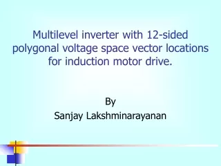
Multilevel inverter with 12-sided polygonal voltage space vector locations for induction motor drive. By Sanjay Lakshminarayanan
Conventional 2-level inverter 1 3 5 Vdc B C A 4 6 2 IM Vr=VA + VB.ej2/3 + VC.ej4/3 Vr= V + j.Vβ CEDT, INDIAN INSTITUTE OF SCIENCE, BANGALORE, INDIA
b-phase 010 110 Vr α 011 100 a-phase 001 101 c-phase Hexagonal voltage space vectors CEDT, INDIAN INSTITUTE OF SCIENCE, BANGALORE, INDIA
Topology of a multilevel inverter for generation of 12-side polygonal voltage space vectors for induction motor drives. Table gives voltage levels at A for different switch conditions in that leg. ‘1’=Switch On, ‘0’=Switch Off ‘0/1’=Don’t care CEDT, INDIAN INSTITUTE OF SCIENCE, BANGALORE, INDIA
Some points on the topology • Consists of three cascaded 2-level inverters • Asymmetrical DC-links are present • Induction motor fed from a single side • Simple structure CEDT, INDIAN INSTITUTE OF SCIENCE, BANGALORE, INDIA
Topology of a multilevel inverter for generation of 12-side polygonal voltage space vectors for induction motor drives. INV1 and INV3 switches need to have a voltage blocking capacity of 0.366kVdc, while INV2 switches need a blocking voltage of 1.0kVdc. CEDT, INDIAN INSTITUTE OF SCIENCE, BANGALORE, INDIA
Generation of voltage space vectors OQ: (310) implies that leg A is 1.366kVdc, B is at 0.366kVdc and C is zero. OP:(301) implies that leg A is at 1.366kVdc, B is zero, C is 0.366kVdc. OS:(230) implies that leg A is at 1.0kVdc and leg B is at 1.366kVdc and C zero. CEDT, INDIAN INSTITUTE OF SCIENCE, BANGALORE, INDIA
E S F R 4 3 5 2 G Q 6 1 7 12 O P 8 H 9 11 10 L I K The radius(OQ, OP etc.) of the space vector is 1.225kVdc so if we find k that makes the radius= 1Vdc as in a hexagonal space vector we get k=1/1.225=0.816 So now the DC-links of 0.366kVdc=0.299Vdc about 30% of Vdc. The other DC-link of 0.634kVdc= 0.517Vdc about 52% of Vdc. The total DC-link is 1.366kVdc=1.115Vdc. CEDT, INDIAN INSTITUTE OF SCIENCE, BANGALORE, INDIA
Hexagonal space vectors. 12-sided polygonal space vectors. 010 110 E S F R 4 3 5 2 G 100 001 Q 6 1 7 12 O P 8 H 101 001 9 11 10 L I K J Maximum linear range of modulation for hexagonal space vectors: Cos(300).(2/3)Vdc=0.577Vdc For 12-sided polygonal space vector: Cos(150).(2/3)Vdc=0.644Vdc Maximum value of the fundamental for hexagonal space vector: 2/πVdc=0.637Vdc. For 12-sided polygonal space vector: 0.988.(2/3)Vdc=0.658Vdc. CEDT, INDIAN INSTITUTE OF SCIENCE, BANGALORE, INDIA
Generating a reference vector of any amplitude and phase E S F R 4 3 5 2 G Vr Q 6 1 7 O P 8 12 H 9 11 10 I L K J Vr=VA + VB.ej2/3 + VC.ej4/3 Vr= V + j.Vβ CEDT, INDIAN INSTITUTE OF SCIENCE, BANGALORE, INDIA
Volt-sec balance equations V: radius of polygon, m:sector number, TS is sampling period CEDT, INDIAN INSTITUTE OF SCIENCE, BANGALORE, INDIA
T1 and T2 are found from the reference voltages • A look-up table can speed up calculations • T1 and T2 along with sector number is sufficient to produce the gate signals of the IGBTs in order to operate the inverter CEDT, INDIAN INSTITUTE OF SCIENCE, BANGALORE, INDIA
Sector Identification ‘Va’ positive ‘Vb-Vc’ positive: 1st quadrant ‘Va’ negative ‘Vb-Vc’ positive: 2nd quadrant ‘Va’ negative ‘Vb-Vc’ negative: 3rd quadrant ‘Va’ positive ‘Vb-Vc’ negative: 4th quadrant CEDT, INDIAN INSTITUTE OF SCIENCE, BANGALORE, INDIA
Sector Identification If in quadrant 1: If |Vb-Vc|<=|Va|.√3.tan150 then sector 1 else If |Vb-Vc|<=|Va|.√3.tan450 then sector 2 else If |Vb-Vc|<=|Va|.√3.tan750 then sector 3 else sector 4 If in quadrant 2: If |Vb-Vc|<=|Va|.√3.tan150 then sector 7 else If |Vb-Vc|<=|Va|.√3.tan450 then sector 6 else If |Vb-Vc|<=|Va|.√3.tan750 then sector 5 else sector 4 CEDT, INDIAN INSTITUTE OF SCIENCE, BANGALORE, INDIA
Sector Identification If in quadrant 3: If |Vb-Vc|<=|Va|.√3.tan150 then sector 7 else If |Vb-Vc|<=|Va|.√3.tan450 then sector 8 else If |Vb-Vc|<=|Va|.√3.tan750 then sector 9 else sector 10 If in quadrant 4: If |Vb-Vc|<=|Va|.√3.tan150 then sector 1 else If |Vb-Vc|<=|Va|.√3.tan450 then sector 12 else If |Vb-Vc|<=|Va|.√3.tan750 then sector 11 else sector 10 CEDT, INDIAN INSTITUTE OF SCIENCE, BANGALORE, INDIA
In order to reduce switching losses the switching frequency is kept low(~1000Hz) using the following sampling sheme: 0<f<=15Hz: 4 samples per sector 15<f<=30Hz: 3 samples per sector 30<f<=45Hz: 2 samples per sector 45<f<=50Hz: 1 sample per sector Where f is the frequency of operation in Hz. Sampling Strategy for PWM CEDT, INDIAN INSTITUTE OF SCIENCE, BANGALORE, INDIA
V/f Control V/f control for the drive This scheme is used to keep the flux in the motor constant irrespective of the speed or frequency of operation. CEDT, INDIAN INSTITUTE OF SCIENCE, BANGALORE, INDIA
Comparison to obtain time durations Once the time durations T1 and T2 are available and the sector number known, this information is sufficient to synthesize all the switch gate pulses using a PAL using combinational logic. CEDT, INDIAN INSTITUTE OF SCIENCE, BANGALORE, INDIA
Simulation results: Pole voltage at 30Hz. • Voltage levels at 0.366kVdc, 1.0kVdc and 1.366kVdc are observed. • Each leg is clamped to the zero state for 30% of the total period. CEDT, INDIAN INSTITUTE OF SCIENCE, BANGALORE, INDIA
Simulation results Phase voltage at 30Hz. CEDT, INDIAN INSTITUTE OF SCIENCE, BANGALORE, INDIA
Pole voltage at 50Hz. (Simulation) • Voltage between pole A and negative bus of bottom-most DC-link • 12-step mode is present, beginning of overmodulation. CEDT, INDIAN INSTITUTE OF SCIENCE, BANGALORE, INDIA
Phase voltage at 50Hz. This shows the twelve step waveform, each space vector is active for 1/12th of the time period before the inverter outputs the next space vector. CEDT, INDIAN INSTITUTE OF SCIENCE, BANGALORE, INDIA
Experimental Setup • The inverter topology was set up using IGBTs with their associated gate drives. • DC links were produced by rectifying 3-phase transformer outputs. • A digital signal processor(DSP), TMS320LF2407A produces the requisite PWM at its PWM output port, and also the sector number(4 bits) is an output • Two PALs synthesize the gate pulses using the output of the DSP. • Dead band circuits were used to provide adequate dead bands for the top and bottom IGBTs in a leg of the inverter. • A 1.5KW, 50Hz three phase induction motor was used to test the inverter. The motor parameters are as below: • M: Magnetising inductance: 0.272 H Lrr: Total rotor inductance: 0.28 H Lss: Total stator inductance: 0.28 H Rs: Stator resisitance: 2.08 ohm Rr: Rotor resistance: 4.19 ohm Number of poles: 4 CEDT, INDIAN INSTITUTE OF SCIENCE, BANGALORE, INDIA
Experimental Results Fig. 1a: Phase voltage and motor current at 15Hz. (X-axis: 1div=20ms, Y-axis: Upper trace: 1div=50V, lower trace: 1div=1.5A) Fig. 1b: Pole voltage at 15Hz. (X-axis: 1div=20ms, Y-axis: Upper trace: 1div=50V, lower trace= 1.5A) CEDT, INDIAN INSTITUTE OF SCIENCE, BANGALORE, INDIA
Experimental results: Phase and Pole voltages Fig. 2b: Pole voltage and motor current at 30Hz. (X-axis: 1div=5ms, Y-axis: Upper trace: 1div=50V, lower trace: 1div=2A) Fig. 2a: Phase voltage and motor current at 30Hz. (X-axis: 1div=10ms, Y-axis: Upper trace: 1div=50V, Lower trace: 1div= 2A) CEDT, INDIAN INSTITUTE OF SCIENCE, BANGALORE, INDIA
Experimental results: Phase and Pole Voltages Fig. 3a: Phase voltage and motor current at 45Hz. (X-axis: 1div=10ms, Y-axis: Upper trace: 1div=100V, Lower trace: 1div=2A) Fig. 3b: Pole voltage at 45Hz. (X-axis: 1div=10ms, Y-axis: Upper trace: 1div=50V, Lower trace: 1div=2A) CEDT, INDIAN INSTITUTE OF SCIENCE, BANGALORE, INDIA
Experimental results Fig. 4a: Phase voltage and motor current at 50Hz. (X-axis: 1div=5ms, Y-axis: Upper trace: 1div=100V, Lower trace: 1div=1A) Fig. 4b: Pole voltage at 50Hz. (X-axis: 1div=5ms, Y-axis: Upper trace: 1div=50V, Lower trace: 1div=2A) CEDT, INDIAN INSTITUTE OF SCIENCE, BANGALORE, INDIA
Harmonics at 15Hz operation. (X-axis: nth harmonic, Y-axis: Relative amplitude) • Note the absence of 5th and 7th and 6n±1, n=1, 3, 5,.. Harmonics • 11th and 13th are highly suppressed • Only 47th is prominent at 10% of fundamental CEDT, INDIAN INSTITUTE OF SCIENCE, BANGALORE, INDIA
Harmonics in 30Hz operation (X-axis: nth harmonic, Y-axis: Relative amplitude) • Only 35th and 37th and 47th and 49th harmonics can be seen. • Motor current waveform will not be affected much by these harmonics. CEDT, INDIAN INSTITUTE OF SCIENCE, BANGALORE, INDIA
Harmonics in 45Hz operation. (X-axis: nth harmonic, Y-axis: Relative amplitude) • 11th and 13th highly suppressed • 23rd, 25th, 35th, 37th, 47th and 49th alone prominent. CEDT, INDIAN INSTITUTE OF SCIENCE, BANGALORE, INDIA
Harmonics in 50Hz operation. (X-axis: nth harmonic, Y-axis: Relative amplitude) • 11th and 13th are about 10% • 23rd and 25th about 5% others lower CEDT, INDIAN INSTITUTE OF SCIENCE, BANGALORE, INDIA
Trends in the Harmonics CEDT, INDIAN INSTITUTE OF SCIENCE, BANGALORE, INDIA
Salient features • Complete elimination of the following harmonics: 5, 7 and 6n±1, n=1, 3, 5.. • Current control is easier to implement as 5th and 7th are absent. • In the 12-step mode of operation the maximum value of the fundamental component achieved is 0.658Vdc against the value 0.637Vdc achieved in the conventional six-step mode of operation. • Linear range of modulation is 0.644Vdc, higher than 0.577Vdc in hexagonal space vector based inverter. • An inverter leg is switched off for 30% of the period, this reduces switch stress. • No need to open machine neutral, can feed from one side. CEDT, INDIAN INSTITUTE OF SCIENCE, BANGALORE, INDIA
Twelve-sided polygonal voltage space vector based multi-level inverter for an induction motor drive with common-mode voltage elimination By Sanjay Lakshminarayanan
Schematic of the proposed power circuit of the inverter fed IM drive • An open-end induction machine is used. • Two three–level inverters (cascading two two-level inverters) are used on either sides of the induction motor windings. • Asymmetrical DC-links of the ratio 1:0.366 are required. CEDT, INDIAN INSTITUTE OF SCIENCE, BANGALORE, INDIA
Asymmetrical DC-link generation Since 0.634=√3*0.366, Star-delta transformers may be arranged as shown to obtain the DC-link voltages. CEDT, INDIAN INSTITUTE OF SCIENCE, BANGALORE, INDIA
Switch states and pole voltage levels in a leg Upper switches such as S11 and S14 require a voltage blocking capacity of 1.0kVdc while lower switches such as S21, S24 need a blocking capacity of 1.366kVdc. CEDT, INDIAN INSTITUTE OF SCIENCE, BANGALORE, INDIA
Switching states from INV-A and INV-B and the resultant space phasors. Note: OP=OQ=1.225kVdc The “dashed” vectors such as OP, OQ, OE, OF, OI and OJ are from INV-A, the solid line vectors such as OR, OS, OG, OH, OK, OL are from INV-B. CEDT, INDIAN INSTITUTE OF SCIENCE, BANGALORE, INDIA
Switching states from INV-A and INV-B and the resultant space phasors. Note: OP=OQ=1.225kVdc OA is 1.366kVdc along A-axis, AQ is 0.366kVdc along B-axis and 0 kVdc along C axis, resultant vector is OQ belonging to INV-A. OB is 1.366kVdc along negative C-axis, BR is 0.366kVdc along negative B-axis, 0 along a-axis, resultant is vector OR which is negative of the INV-B space vector. CEDT, INDIAN INSTITUTE OF SCIENCE, BANGALORE, INDIA
Generation of 12-sided polygonal voltage space phasor with common-mode voltage elimination • Vectors from INV-A and INV-B are added so that the common-mode voltage on both sides are the same. Alternate vectors from INV-A( dashed line) and INV-B( solid line) are taken and added to get the resultant space vectors numbered 1 to 12 above. Note: OP=OQ=1.225kVdc CEDT, INDIAN INSTITUTE OF SCIENCE, BANGALORE, INDIA
Generation of 12-sided polygonal voltage space phasor with common-mode voltage elimination 12 polygonal space phasors are obtained with zero common-mode voltage variation. Note: OP=OQ=1.225kVdc 2.OP.cos(300)=OR OR=√3.OP CEDT, INDIAN INSTITUTE OF SCIENCE, BANGALORE, INDIA
2.OP.cos(300)=OR OR=√3.OP The resultant space vector has magnitude OR=√3.OP, since OP=1.225kVdc we can find ‘k’ to make OR equal to Vdc as in hexagonal space vectors from a 2-level inverter. k=1/(1.225*√3) k=0.471, so the upper DC-link voltage(1.0kVdc) is 0.471Vdc and the lower DC-link voltage(0.366kVdc) is 0.172Vdc. This implies that lower voltage devices can be used for a given Vdc than in other schemes for generation of 12-sided polygonal space vectors. CEDT, INDIAN INSTITUTE OF SCIENCE, BANGALORE, INDIA
Summary of levels required in INV-A and INV-B to achieve the 12 space vectors CEDT, INDIAN INSTITUTE OF SCIENCE, BANGALORE, INDIA
Common-mode voltage elimination In any of the space vector locations from ‘1’ to ‘12’, the pole voltages in INV-A and INV-B, sum up to the same common-mode voltage (1.366kVdc+0.366kVdc+0kVdc)/3 =(1.732/3)kVdc The resultant common-mode voltage in the phase windings is zero CEDT, INDIAN INSTITUTE OF SCIENCE, BANGALORE, INDIA
Comparison of 12-sided spacevector with hexagonal space vector Hexagonal space vectors. 12-sided polygonal space vectors. 010 110 E S F R 4 3 5 2 G 100 001 Q 6 1 7 12 O P 8 H 101 001 9 11 10 L I K J Maximum linear range of modulation for hexagonal space vectors: Cos(300).(2/3)Vdc=0.577Vdc For 12-sided polygonal space vector: Cos(150).(2/3)Vdc=0.644Vdc Maximum value of the fundamental for hexagonal space vector: 2/πVdc=0.637Vdc. For 12-sided polygonal space vector: 0.988.(2/3)Vdc=0.658Vdc. CEDT, INDIAN INSTITUTE OF SCIENCE, BANGALORE, INDIA
E S F R 4 3 5 2 G Vr Q 6 1 7 O P 8 12 H 9 11 10 I L K J 12-sided polygonal space vectors and a reference vector If we have three sinusoidal reference voltages VA, VB and VC 1200 apart in time the resulting space vector Vr rotates around the origin. Vr=VA + VB.ej2/3 + VC.ej4/3 Vr= V + j.Vβ CEDT, INDIAN INSTITUTE OF SCIENCE, BANGALORE, INDIA
Volt-sec balance equations V: radius of polygon, m:sector number, TS is sampling period CEDT, INDIAN INSTITUTE OF SCIENCE, BANGALORE, INDIA
Volt-sec balance equations For the case when vector 1 is in line with -axis CEDT, INDIAN INSTITUTE OF SCIENCE, BANGALORE, INDIA
Expressions for T1 and T2 in each sector CEDT, INDIAN INSTITUTE OF SCIENCE, BANGALORE, INDIA
Sector identification The quadrant in which the reference vector lies can be Found from the phase voltages as below- ‘vA’ positive, and ‘(vB-vC )’ positive: 1st quadrant. ‘vA’ negative, and ‘(vB-vC)’ positive: 2nd quadrant. ‘vA’ negative, ‘(vB-vC)’ negative: 3rd quadrant. ‘vA’ positive, ‘(vB-vC)’ negative: 4th quadrant. CEDT, INDIAN INSTITUTE OF SCIENCE, BANGALORE, INDIA