Wireless link
Explore the images of the small bowel captured by capsule endoscopy, including views of different segments and the design of the endoscope system. Learn about the wireless link, data processing, and image retrieval process.

Wireless link
E N D
Presentation Transcript
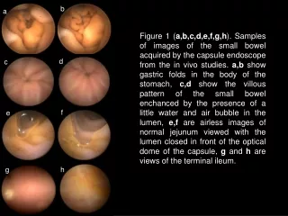
b a Figure 1 (a,b,c,d,e,f,g,h). Samples of images of the small bowel acquired by the capsule endoscope from the in vivo studies. a,b show gastric folds in the body of the stomach, c,d show the villous pattern of the small bowel enchanced by the presence of a little water and air bubble in the lumen, e,f are airless images of normal jejunum viewed with the lumen closed in front of the optical dome of the capsule, g and h are views of the terminal ileum. d c f e g h
Wireless link Wired link Capsule Recorder and antennae Workstation Figure 2. Design of the capsule endoscope system: Video capsule, Receiver & Recorder, Workstation.
WORK STATION CAPSULE RECORDER Data storage Optics and Illumination CPU PC Software Imager Digital processing Display Transmitter Receiver Figure 3. Block diagram of the capsule endoscope system. In the first stage the capsule acquires the images. The object is illuminated by the LED illumination system, and the image is projected on the imager by an optical system. The image is then transmitted outside the body by means of the transmitter and antenna. In the second stage antennae array and the receiver collect the transmitted signal. The received data is subsequently processed and stored in the data storage by CPU. In the third stage the date is retrieved from the recorder and transferred to the Workstation for additional processing and presentation on the display. Antenna Antennae array
a b c d e f g h Figure 4. a,b - epiglottis. c,d - esophagus. e - stomach, gastric folds. f - intestine. g,h - caecum. i - large intestine, no preparation was performed - content of large intestine is visible. i