WP6: Anaprop Modelling
WP6: Anaprop Modelling. U. Essex / UBC. Overview. Part I --- Anaprop Cases Part II – DEM Interaction Part III - Terrain Interaction. Examples of ANAPROP…. Interpolation Issues. Refractive index must be computed efficiently as a continuous or smooth

WP6: Anaprop Modelling
E N D
Presentation Transcript
WP6: Anaprop Modelling U. Essex / UBC Carpe Diem, Dublin Dec 2003
Overview • Part I --- Anaprop Cases • Part II – DEM Interaction • Part III - Terrain Interaction Carpe Diem, Dublin Dec 2003
Examples of ANAPROP… Carpe Diem, Dublin Dec 2003
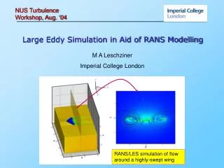
Interpolation Issues Refractive index must be computed efficiently as a continuous or smooth function of position, interpolated in horizontal and vertical. Ray plane M(z) Vertical profile o(100m) NWP Levels are not spatial - s coordinates. Modified Akima Bicubic interpolation Vertical Cubic Splines Plan view o(10km) spacing of NWP gridpoints Carpe Diem, Dublin Dec 2003
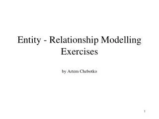
Catalunya Topography Carpe Diem, Dublin Dec 2003
Geodetic rectification DEM is expressed in geographic coordinates. Radar coordinates (tangential plane) need to be rectified to DEM coordinate system. - Spherical correction of order 1 km - Elliptical correction of order one or two DEM grid points Carpe Diem, Dublin Dec 2003
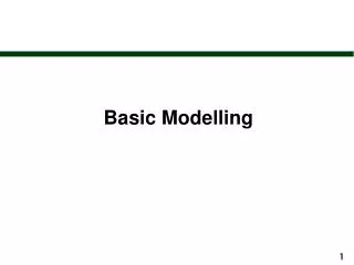
Catalunya DEM radial profiles: range interval 5 km, azimuth interval 10 degrees Carpe Diem, Dublin Dec 2003
Catalunya DEM radial profiles: range interval 5 km, azimuth interval 2 degrees Carpe Diem, Dublin Dec 2003
Catalunya DEM radial profiles: range interval 5 km, azimuth interval 2 degrees Carpe Diem, Dublin Dec 2003
Catalunya DEM radial profiles: range interval 5 km, azimuth interval 2 degrees Carpe Diem, Dublin Dec 2003
Catalunya DEM radial profiles: range interval 5 km, azimuth interval 2 degrees Carpe Diem, Dublin Dec 2003
Part II - Terrain Interaction • Simulation of ANAPROP requires a good model of terrain profile model of terrain • profile for each radar azimuth. • - need to determine where beam interacts with terrain • -where terrain sufficiently smooth, evaluate coherent forward reflection • propagating to further targets • Tasks in hand/completed • Interpolation from cartesian to polar grid. • B-spline interpolation/approximation of terrain profiles Carpe Diem, Dublin Dec 2003
Wave surfaces at interfaces incident wave surface local tangent plane Wave surfaces link as a sparse tree structure Surface impresses phase on child Wave surface reflected wave surface: Carpe Diem, Dublin Dec 2003
Modelling of Reflection • Asymptotic calculation • Two types of contribution: • Phase Integral • Residue series Phase Integral Combines phase paths and the Fresnel reflection factor Residue series Relates to surface resonances (evanescent modes) – we ignore these in evaluating far field propagated waves Carpe Diem, Dublin Dec 2003
Orthotomic reference Phase integral for a source can be represented as summation of image sources located on the orthotomic curve with respect to source and reflecting surface. Point of tangency source In general, the orthotomic image in a general surface is complex For radar scattering geometry – low incidence angle, long range, the orthotomic image points lie close to a circle. image Carpe Diem, Dublin Dec 2003
Undulating Terrain inversion Fit to conformal orthotomic map Carpe Diem, Dublin Dec 2003
Phase compensation simulation shows that the Phase errors vary smoothly with position We arrive at a unified approach to evaluating the reflected field by creating a wave-surface object on the best-fit orthotomic circle Carpe Diem, Dublin Dec 2003
Part III – Further work • Gauging effectiveness of anaprop modelling depends on visualization of results. • Anaprop is strongly linked to terrain, so it is desirable to have simultaneous display of terrain and radar. • developed PostScript transparent radar overlay • show terrain in ‘brownscale’ • developed polar contour module for 3rd variable, e.g - anaprop reflectivity • developed image warping transformations to display lat-lon terrain data in radar tangent-plane coordinates Carpe Diem, Dublin Dec 2003
Backscatter Modelling • High resolution Catalan DEM (30 m) also provides • land cover data. • help parametrize surface reflectivity • grazing angle dependence strongly influenced by cover almost specular: very low angle backscatter small highly diffuse (a) grass (b) tree(s) Carpe Diem, Dublin Dec 2003
Summary Ongoing development of a software tool to simulate and visualize anaprop predicted on the basis of NWP data. Design concepts geared to: (a) highly efficient evaluation of the beam propagation - wave surface data structure - polynomial reps of n, h, rays. (b) parametric variation Further developments will be aimed at optimization of match between observation and NWP, with possible refinements of NWP data Carpe Diem, Dublin Dec 2003