Download
1 / 13
130 likes | 303 Views
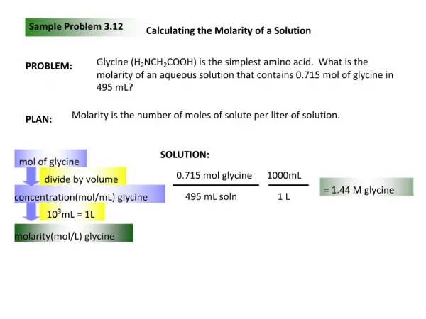
SOLUTION: Based on the cross section geometry, calculate the location of the section centroid and moment of inertia. Apply the elastic flexural formula to find the maximum tensile and compressive stresses.

E N D
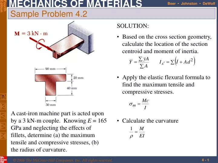
SOLUTION: • Based on the cross section geometry, calculate the location of the section centroid and moment of inertia. • Apply the elastic flexural formula to find the maximum tensile and compressive stresses. A cast-iron machine part is acted upon by a 3 kN-m couple. Knowing E = 165 GPa and neglecting the effects of fillets, determine (a) the maximum tensile and compressive stresses, (b) the radius of curvature. • Calculate the curvature Sample Problem 4.2
Sample Problem 4.2 SOLUTION: Based on the cross section geometry, calculate the location of the section centroid and moment of inertia.
Apply the elastic flexural formula to find the maximum tensile and compressive stresses. • Calculate the curvature Sample Problem 4.2
Consider a composite beam formed from two materials with E1 and E2. • Normal strain varies linearly. • Piecewise linear normal stress variation. Neutral axis does not pass through section centroid of composite section. • Elemental forces on the section are • Define a transformed section such that Bending of Members Made of Several Materials
Bar is made from bonded pieces of steel (Es = 29x106 psi) and brass (Eb = 15x106 psi). Determine the maximum stress in the steel and brass when a moment of 40 kip*in is applied. Example 4.03 • SOLUTION: • Transform the bar to an equivalent cross section made entirely of brass • Evaluate the cross sectional properties of the transformed section • Calculate the maximum stress in the transformed section. This is the correct maximum stress for the brass pieces of the bar. • Determine the maximum stress in the steel portion of the bar by multiplying the maximum stress for the transformed section by the ratio of the moduli of elasticity.
SOLUTION: • Transform the bar to an equivalent cross section made entirely of brass. • Evaluate the transformed cross sectional properties • Calculate the maximum stresses Example 4.03
In the transformed section, the cross sectional area of the steel, As, is replaced by the equivalent areanAswhere n = Es/Ec. • To determine the location of the neutral axis, • The normal stress in the concrete and steel Reinforced Concrete Beams • Concrete beams subjected to bending moments are reinforced by steel rods. • The steel rods carry the entire tensile load below the neutral surface. The upper part of the concrete beam carries the compressive load.
A concrete floor slab is reinforced with 5/8-in-diameter steel rods. The modulus of elasticity is 29x106psi for steel and 3.6x10⁶psi for concrete. With an applied bending moment of 40 kip*in for 1-ft width of the slab, determine the maximum stress in the concrete and steel. Sample Problem 4.4 • SOLUTION: • Transform to a section made entirely of concrete. • Evaluate geometric properties of transformed section. • Calculate the maximum stresses in the concrete and steel.
SOLUTION: • Transform to a section made entirely of concrete. • Evaluate the geometric properties of the transformed section. • Calculate the maximum stresses. Sample Problem 4.4
Stress Concentrations • Stress concentrations may occur: • in the vicinity of points where the loads are applied • in the vicinity of abrupt changes in cross section
For any member subjected to pure bending strain varies linearly across the section • If the member is made of a linearly elastic material, the neutral axis passes through the section centroid and • For a material with a nonlinear stress-strain curve, the neutral axis location is found by satisfying Plastic Deformations • For a member with vertical and horizontal planes of symmetry and a material with the same tensile and compressive stress-strain relationship, the neutral axis is located at the section centroid and the stress-strain relationship may be used to map the strain distribution from the stress distribution.
The modulus of rupture in bending, RB, is found from an experimentally determined value of MU and a fictitious linear stress distribution. Plastic Deformations • When the maximum stress is equal to the ultimate strength of the material, failure occurs and the corresponding moment MU is referred to as the ultimate bending moment. • RB may be used to determine MU of any member made of the same material and with the same cross sectional shape but different dimensions.
Rectangular beam made of an elastoplastic material • If the moment is increased beyond the maximum elastic moment, plastic zones develop around an elastic core. • In the limit as the moment is increased further, the elastic core thickness goes to zero, corresponding to a fully plastic deformation. Members Made of an Elastoplastic Material