Download
1 / 13
130 likes | 224 Views
Explore the process of designing systems by defining, implementing subsystems, mapping hardware/software platforms, managing data, and access control policies. Learn about global control flow and boundary conditions.

E N D
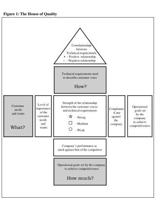
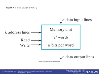
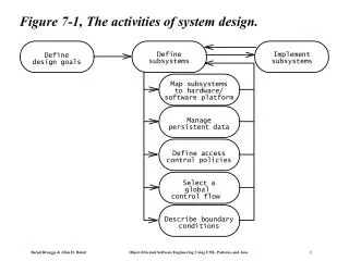
Figure 7-1, The activities of system design. Define Implement Define subsystems subsystems design goals Map subsystems to hardware/ software platform Manage persistent data Define access control policies Select a global control flow Describe boundary conditions
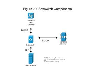
:Safari myMac:Mac :UnixHost :WebServer :UnixHost aPC:PC :Database :IExplorer Figure 7-2, A UML deployment diagram representing the allocation of components to different nodes and the dependencies among components.
WebServer GET URL POST DBQuery HttpRequest DBResult File Figure 7-3, Refined view of the WebServer component.
:OnBoardComputer :WebServer PlanningSubsystem RoutingSubsystem Figure 7-4, Allocation of MyTrip subsystems to hardware.
PlanningSubsystem RoutingSubsystem RouteAssistant PlanningService Trip Location Destination TripProxy Direction Crossing SegmentProxy Segment CommunicationSubsystem Message Connection Figure 7-5, Revised design model for MyTrip.
RoutingSubsystem PlanningSubsystem CommunicationSubsystem TripFileStoreSubsystem MapDBStoreSubsystem Figure 7-6, Subsystem decomposition of MyTrip after deciding on the issue of data stores.
Figure 7-8, Packet filtering firewall: a filter, located at the router, allows or denies individual packets based on header information, such as source and destination.
Access isAccessible(op) 1 Broker * PortfolioProxy Portfolio buy() buy() sell() sell() 1 1 estimateYield() estimateYield() Figure 7-9, Dynamic access implemented with a protection Proxy.
Intruder Legitimate User Server Plaintext message CC# 1234 5678 9012 3456 EXP 8/99 Encrypted message XZ<ASL@#34HF*(*A2135SDA*}BKDAWR#%_AS2255 Figure 7-10, Passive attack. Given current technology, it is relatively easy for a passive intruder to listen to all network traffic. To prevent this kind of attack, encryption makes the information an intruder sees difficult to understand.
ManageDrivers <<include>> ManageMaps StartServer PlanningService <<include>> Administrator ManageServer ShutdownServer <<include>> ConfigureServer Figure 7-14, Administration use cases for MyTrip.
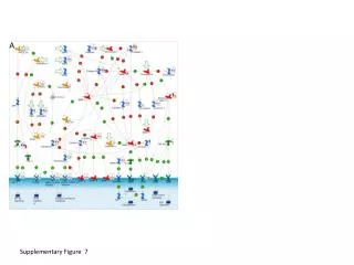
Figure 7-18, ARENA subsystem decomposition, game organization part.
Figure 7-19, ARENA subsystem decomposition, game playing part.