Download
1 / 16
160 likes | 277 Views
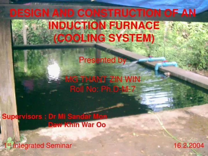
DESIGN AND CONSTRUCTION OF AN INDUCTION FURNACE (COOLING SYSTEM). Presented by MG THANT ZIN WIN Roll No: Ph.D-M-7. Supervisors : Dr Mi Sandar Mon Daw Khin War Oo. 1 st Integrated Seminar 16.2.2004.

E N D
DESIGN AND CONSTRUCTION OF AN INDUCTION FURNACE(COOLING SYSTEM) Presented by MG THANT ZIN WIN Roll No: Ph.D-M-7 Supervisors : Dr Mi Sandar Mon Daw Khin War Oo 1st Integrated Seminar 16.2.2004
Cooling Systems for Electric Induction Furnace • Cooling Pond System • Open-circuit System with Evaporative Cooling Tower • Spray Pond System • Fan-radiator (Closed-circuit) System • Dual System with Water/Water Heat Exchanger • Dual System with Closed-circuit Cooling Tower
Cooling Pond System It is used in UNIDO induction furnace. • Advantages • Simplicity • Small investment • Low noise control • Disadvantages • Large ground area • Less effective in warm ambient conditions • Not suitable for continuous thermal duty
Open-circuit System with Evaporative Cooling Tower Pump Furnace and Ancillaries Buffer Tank Cooling Tower Pump Fig – Open-circuit system with evaporative cooling tower
Types of Cooling Tower Natural Circulation Cooling Tower Mechanical Draft Cooling Tower Forced Draft Induced Draft Atmospheric Natural Draft Counterflow Crossflow
(b) Forced Draft (a) Induced Draft (d) Natural Draft (c) Atmospheric Fig - Common Types of Cooling Tower (f) Crossflow (e) Counterflow
Mechanical Draft Counterflow Cooling Tower Outlet Air • Function • Principles Water Inlet Air Inlet Air Fig – Illustration of a counterflow tower
Cooling Tower Theory Heat is transferred from water drops to the surrounding air by the transfer of sensible and latent heat. Fig – Water drop with interfacial film
Merkel Equation Tower characteristic value, where, K = mass transfer coefficient, lb water/ (h.ft2) a = contact area, ft2/ft3 tower volume V = active cooling volume, ft3/ft2 of plan area L = water rate, lb/ (h.ft2) hw = enthalpy of air-water vapor-mixture at bulk water temperature, Btu/lb dry air ha = enthalpy of air-water vapor-mixture at wet bulb temperature, Btu/lb dry air
Graphical Representation of Tower Characteristic Fig – Cooling tower process heat balance (Markey Co)
Example Calculation KaV/L = ?, Hot water = 105°F, Cold water = 85°F, Ambient web bulb temperature = 78°F, L/G = 0.97 From air-water vapor-mixture tables, h1 (entering air) at 78°F wet bulb temperature = 41.58 Btu/lb h2 (leaving air) = 41.58 + 0.97(105-85) = 60.98 Btu/lb
Nomograph Method Hot water = 100°F, Cold water = 80°F, Wet bulb temp: = 70°F, L/G = 1 So, (KaV)/L = 1.42 # Fig - Nomograph of cooling tower characteristics [Wood and Belts, Engineer, 189(4912), 337 (1950)]
Summary for Cooling Towers • A change in wet bulb temperature (due to atmospheric conditions) will not change the tower characteristic (KaV/L). • A change in the cooling range will not change KaV/L. • Only a change in the L/G ratio will change KaV/L.