Download
1 / 22
1.89k likes | 5.38k Views
4.7 MULTILEVEL INVERTERS (MLI). Main feature Ability to reduce the voltage stress on each power device due to the utilization of multiple levels on the DC bus Important when a high DC side voltage is imposed by an application (e.g. traction systems)

E N D
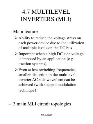
4.7 MULTILEVEL INVERTERS (MLI) • Main feature • Ability to reduce the voltage stress on each power device due to the utilization of multiple levels on the DC bus • Important when a high DC side voltage is imposed by an application (e.g. traction systems) • Even at low switching frequencies, smaller distortion in the multilevel inverter AC side waveform can be achieved (with stepped modulation technique) • 3 main MLI circuit topologies NAA-2002
MLI (2) • Diode-clamped multilevel inverter (DCMI) • Extension of NPC • Based on concept of using diodes to limit power devices voltage stress • Structure and basic operating principle • Consists of series connected capacitors that divide DC bus voltage into a set of capacitor voltages • A DCMI with nl number of levels typically comprises (nl-1) capacitors on the DC bus • Voltage across each capacitor is VDC/(nl-1) ( nl nodes on DC bus, nl levels of output phase voltage , (2nl-1) levels of output line voltage) NAA-2002
MLI (3) NAA-2002
MLI (4) • Output phase voltage can assume any voltage level by selecting any of the nodes • DCMI is considered as a type of multiplexer that attaches the output to one of the available nodes • Consists of main power devices in series with their respective main diodes connected in parallel and clamping diodes • Main diodes conduct only when most upper or lower node is selected • Although main diodes have same voltage rating as main power devices, much lower current rating is allowable • In each phase leg, the forward voltage across each main power device is clamped by the connection of diodes between the main power devices and the nodes NAA-2002
MLI (5) • Number of power devices in ON state for any selection of node is always equal to (nl-1) • Output phase voltage with corresponding switching states of power devices for a 5-level DCMI NAA-2002
MLI (6) • General features • For three-phase DCMI, the capacitors need to filter only the high-order harmonics of the clamping diodes currents , low-order components intrinsically cancel each other • For DCMI employing step modulation strategy, if nl is sufficiently high, filters may not be required at all due to the significantly low harmonic content • If each clamping diode has same voltage rating as power devices, for nl-level DCMI, number of clamping diodes/phase = (nl-1) x (nl-2) • Each power device block only a capacitor voltage NAA-2002
MLI (7) • Clamping diodes block reverse voltage (Dc1, Dc2, Dc3 block VDC/4, 2VDC/4 and 3VDC/4 respectively) • Unequal conduction duty of the power devices • DCMI with step modulation strategy have problems stabilizing/balancing capacitor voltages • Average current flowing into corresponding inner nodes not equal to zero over one cycle • Not significant in SVC applications involving pure reactive power transfer NAA-2002
MLI (8) • Overcoming capacitor voltage balancing problem • Line-to-line voltage redundancies (phase voltage redundancies not available due to structure) • Carefully designed modulation strategies • Replace capacitors with controlled constant DC voltage source such as PWM voltage regulators or batteries • Interconnection of two DCMIs back-to-back with a DC capacitor link (suitable for specific applications only – UPFC, frequency changer, phase shifter) NAA-2002
MLI (9) • Imbricated cell multilevel inverter • Capable of solving capacitor voltage unbalance problem and excessive diode count requirement in DCMI • Also known as flying capacitor multilevel inverter (capacitors are arranged to float with respect to earth) • Structure and basic operating principle • Employs separate capacitors precharged to [(nl-1)/(nl-1)xVDC], [(nl-2)/(nl-1)xVDC] …{[nl-(nl-1)]/[nl-1]xVDC} • Size of voltage increment between two capacitors defines size of voltage steps in ICMI output voltage waveform NAA-2002
MLI (10) • nl-level ICMI has nl levels output phase voltage and (2nl-1) levels output line voltage NAA-2002
MLI (11) • Output voltage produced by switching the right combinations of power devices to allow adding or subtracting of the capacitor voltages • Constraints : capacitors are never shorted to each other and current continuity to the DC bus capacitor is maintained • 5-level ICMI – 16 power devices switching combinations (SWC) . To produce VDC and 0 (1 SWC – all upper devices ON, all lower devices ON), VDC/2 (6 SWC), VDC/4 and 3VDC/4 (4 SWC) • Example - capacitor voltage combinations that produce an output phase voltage level of VDC/2 NAA-2002
MLI (12) VDC - VDC/2 VDC – 3VDC/4 + VDC/4 VDC - 3VDC/4 +VDC/2 – VDC/4 3VDC/4 – VDC/2 + VDC/4 3VDC/4 – VDC/4 VDC/2 • Power devices switching states of a 5-level ICMI NAA-2002
MLI (13) • General features • With step modulation strategy, with sufficiently high nl, harmonic content can be low enough to avoid the need for filters • Advantage of inner voltage levels redundancies - allows preferential charging or discharging of individual capacitors, facilitates manipulation of capacitor voltages so that their proper values are maintained • Active and reactive power flow can be controlled (complex selection of power devices combination, switching frequency/losses for the former) • Additional circuit required for initial charging of capacitors NAA-2002
MLI (14) • Assuming each capacitor used has the same voltage rating as the power devices, nl-level ICMI requires: (nl – 1) x (nl – 2)/2 auxiliary capacitors per phase (nl – 1) main DC bus capacitors • Unequal conduction duty of power devices • Modular structured multilevel inverter (MSMI) • Referred to as cascaded-inverters with Separate DC Sources (SDCs) or series connected H-bridge inverters • Structure and basic operating principle NAA-2002
MLI (15) • Consists of (nl–1)/2 or h number of single-phase H-bridge inverters (MSMI modules) • MSMI output phase voltage Vo = Vm1 + Vm2 + …….. Vmh Vm1 : output voltage of module 1 Vm2 : output voltage of module 2 Vmh : output voltage of module h • Structure of a single-phase nl-level MSMI NAA-2002
MLI (16) NAA-2002
MLI (17) • Power devices switching states of a 5-level MSMI NAA-2002
MLI (18) • General features • Known to eliminate the excessively large number of bulky transformers required by the multipulse inverters, clamping diodes required by the DCMIs and capacitors required by the ICMIs • Simple and modular configuration • Requires least number of components • Comparison of power devices requirements per phase leg among three MLI (assuming all power devices have same voltage rating, not necessary same current rating, each MSMI module represented by a full-bridge, DCMI and ICMI use half-bridge topology) NAA-2002
MLI (19) • Flexibility in extending to higher number of levels without undue increase in circuit complexity simplifies fault finding and repair, facilitates packaging • Requires DC sources isolated from one another for each module for applications involving real power transfer • Adaptation measures have to be taken in complying to the separate DC sources requirement for ASDs applications NAA-2002
MLI (20) • Feed each MSMI module from a capacitively smooth fully controlled three-phase rectifier, isolation achieved using specially designed transformer having separate secondary windings/module • Employ a DC-DC converter with medium to high frequency transformers (between rectifier output and each MSMI module input), allows bidirectional power flow • Isolated DC sources not required for applications involving pure reactive power transfer (SVG) pure reactive power drawn, phase voltage and current 90º apart balanced capacitor charge and discharge NAA-2002
MLI (21) • Originally isolated DC voltages, alternate sources of energy (PV arrays, fuel cells) • Advantage of availability of output phase voltage redundancies • Allows optimised cyclic use of power devices to ensure symmetrical utilization, symmetrical thermal problems and wear • Design of power devices utilization pattern possible • Overall improvement in MSMI performance – high quality output voltage etc. NAA-2002
MLI (22) • Modulation strategies for multilevel inverters • Step modulation • Space vector modulation • Optimal/programmed PWM technique • Sigma delta modulation (SDM) • High-dynamic control strategies • Multilevel hysterisis modulation strategy • Sliding mode control based on theory of Variable Structure Control System (VSCS) NAA-2002