Download
1 / 25
270 likes | 510 Views
Carbon Sequestration in Sedimentary Basins Module V: Carbon Dioxide Storage in Salt Caverns. Maurice Dusseault Department of Earth Sciences University of Waterloo. Why Salt Caverns for CO 2 ?. In areas where other options limited In areas with suitable salt deposits

E N D
Carbon Sequestrationin Sedimentary BasinsModule V: Carbon Dioxide Storage in Salt Caverns Maurice Dusseault Department of Earth Sciences University of Waterloo
Why Salt Caverns for CO2? • In areas where other options limited • In areas with suitable salt deposits • Near point sources of CO2 • Heavy oil upgrading facilities, cement • Coal-fired power plants, gasification • Steel manufacture, petrochemical plants • Caverns can pay for themselves • NaCl brine has value • Facilities’ CAPEX can be amortized
Cavern Design • Integrity • Stability • Security • Safety • Longevity • … • … overburden limestone, shale salt shale, anhydrite casing shoe roof salt, >25 m z - depth roof span H ~ 75-100 m 15 m internal pressure pi bounding ellipsoid D ~ 100 m approximate cavern shape rubble floor salt, >10 m
Caverns: Temporary Storage… • Salt cavern integrity is difficult to guarantee in perpetuity • Hence, salt caverns with supercritical CO2 are considered temporary storage • Seasonal (12-month cycle, several years), in order to smooth transshipment needs • Generational (20-100 years), to store excess CO2 until disposal or use is possible • Long-term (50-500 yrs), but likely not longer because of uncertainty
A Typical Case History:The Lotsberg Salt:Location and Geology
Geological Environment Western Canadian Sedimentary Basin Tectonically stable Thick, pure salt deposits >95% NaCl in Lotsberg 3 salt zones (security) Overlying competent rock Close to CO2 point sources
Major CO2 Point Sources Synthetic crude and Petrochemical sites Coal-fired power sites Alberta WHERE? Prairie Formation Salt Deposit Athabasca Oil Sands Cold Lake Oil Sands Wabiskaw Deposits Heavy Oil Belt LOTSBERGSALT Edmonton Calgary Saskatchewan
Lithostratigraphy Overburden strata Prairie Salt, excellent flow barrier Dolomites and shales, one aquifer Cold Lake Salt, excellent barrier Low-k roof beam Ernestina Lk Fmn Lotsberg Salt – 160 m of pure salt Underburden, dense silts, shales
Approach to pct Analysis • Numerical models are inaccurate • Numerical dispersion for long times • Local discretization leads to errors • New semi-analytical model developed • Viscoelastic salt behavior, n = 3 • Coupled to Peng-Robinson EOS • Idealized spherical or ellipsoidal shape • Infinite salt half-space
Salt Deformation Behavior Transient creep only for the first few weeks Steady-state creep after a few weeks of a Dp Increasing shear stress (~ - pc) = faster creep Strain Extremely slow creep rates when cavern pressure approaches the regional stress Time
Steady-State Creep Law • ss = steady-state creep rate • = initial stress in salt • pc = pressure in the CO2 in cavern • A, o = material-dependent constants • n = creep law exponent • The critical parameter in creep predictions • = 3.0, based on mine back-calculations • Also, from data on long-term lab creep tests
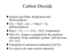
Equation of State for CO2 Experimental phase behavior data for pure CO2 For analysis, we coupled cavern closure behavior to CO2 compressi-bility using the Peng-Robinson EOS
pc t for Cavern Closure pc =1.0 sv 1.0 1.0 0.8 0.8 0.6 0.6 Normalized cavern pressure pc = 0.5sv 0.4 0.4 0.2 0.2 Time in years 0 0 1000 1000 2000 2000 3000 3000 4000 4000
Cavern Pressure Response • CO2 is always in a supercritical state • Salt exhibits slow creep closure • Slow closure gradually pressurizes CO2 • Long-term pressure response is only weakly sensitive to filling pressure • In ~4000 years, pc ~ 94% of sv • Final density approaches 0.92 g/cm3
Subsidence at the Surface? Greatest subsidence will be right above the cavern for the case of a single cavern Subsidence will decay to negligible values at distances greater than 5Z from the cavern location For an array of caverns, the subsidence depends on how many caverns, at what spacings, & the DV/Dt Z ~ 1200 m spacing 100 m diameter
Subsidence Response • For the following case: • Single 100 m Ø cavern, Vi ~ 500,000 m3 • Filled to 14 MPa (pressure of a brine column to the surface) • Cavern sealed in perpetuity • Volume change in cavern ~ 78,000 m3 • 2.5 mm displacement in first 150 yrs • 2.5 mm thereafter (as t )
brines, r = 1.2 Leakage Mechanisms wellbore fresh water, r = 1.0 low permeability Dp advection high permeability wellbore leakage fracture salt permeable interbeds
0 100 200 300 400 500 600 700 800 900 1000 1100 1200 1300 1400 1500 Security? Glacial and Recent strata Cretaceous and Tertiary sands, silts and shales. Karstic erosion surface Devonian carbonate strata Prairie Evaporites, Keg River, Chinchaga Fmns. Cold Lake Formation Ernestina Lake Fmn Lotsberg Salt Basal Red Beds Igneous, metamorphic rocks Ductile shales (kv ~ 0) Flat-lying strata No faults, folds Massive salts (kv = kh ~ 0) Depth in Metres
Regional Storage Security • Regionally ~ flat-lying strata • Three integral massive salt seals • Permeability to gas = 0 • Great lateral extent (100s of km) • No faults or folds • Ductile shales, depths of 200-400 m • Water-filled porous strata • CO2 can go into solution if it escapes
Secure Cavern Design Overlying salt beds Non-shrinking, ductile cement Special squeezed cement seals Salt-occluded porosity in bounding strata 25-35 m overlying salt barrier 90-100 m high “spherical” cavern Thick lateral salt beds 15-20 m lower salt barrier Salt-occluded porosity in Red Beds
Cavern-Scale Security • Proper site location • Salt barriers (30-40 m overlying) • Occluded porosity in adjacent strata • Salt infills the porosity in bounding beds • ~Spherical shape (max ellipticity 1.5) • Ductile non-shrinking casing cement • Installation of high pressure squeezed cement plugs • Etc
CONCLUSIONS • The Lotsberg Salt is an exceptionally favorable deposit for CO2 storage • The regional geology also is favorable • Two caverns (~106 m3) could take Al-berta point CO2 emissions for 5 years • Analysis shows that >4000 years are needed for pressure 95% of sv • Filling and sealing are relatively straightforward technically
Some Predictions… • Generally available competitive H2 fuel cell cars at least 20 years away • Biosolids injection will be a huge industry in 30-40 years • Separation, deep injection of gaseous, supercritical CO2 may happen…(?) • Nuclear energy is poised for a major comeback (no CO2!) • Taxes are going to go up