Download
1 / 6
60 likes | 229 Views
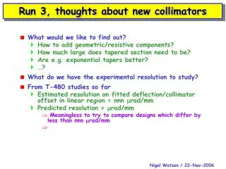
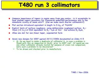
T480 run 3 collimators. Compare importance of tapers in region away from gap centre – is it acceptable to have shallow tapers necessary for transverse wakefield performance only in the immediate vicinity of beam axis?? (Can we make much shorter collimators?)

E N D
T480 run 3 collimators • Compare importance of tapers in region away from gap centre – is it acceptable to have shallow tapers necessary for transverse wakefield performance only in the immediate vicinity of beam axis?? (Can we make much shorter collimators?) • Flat section introduced equivalent in length to 0.6c0 of Ti6Al4V • Explicit tests of surface roughness, using deliberately roughened surface, Ra~ 10mm (~0.1sy) at ESA equivalent to Ra~ 1mm at ILC. Can achieve Ra~6mm. • Allow one slot for non-linear taper, exponential form • Seven new designs for 2007 agreed 22/11//2006 documented on slides 4-5 • Q: Do we need to make a duplicate of collimator 6, in case a problem is found with this on inspection at SLAC, prior to 2007 run? Or would we use any other collimator already tested for purpose of cross-run comparison, were such a problem to be discovered? • To be drawn and checked prior to manufacture.
38 mm h=38 mm L=1000 mm a r=1/2 gap As per last set in Sector 2, commissioning Runs 1-2 Extend last set, smaller r, resistive WF in Cu 7mm cf. same r, tapered
38 mm 7 mm cf. collim. 4 smaller r h=38 mm cf. collim. 2, same r 211mm 31mm cf. collims. 4 and 6 133mm cf. collim. 7, and same step in/out earlier data Runs 1-2
~211mm a a a a 38 mm 1.4mm h=38 mm =21mm =21mm =21mm Exists, from 2006 runs. For reproducibility Runs 3, 2007 Roughened surface, compare with 12 As 10, in Ti-6Al-4V, polished, cf. 12 As 10, in OFE Cu, polished, cf. collim. 6, 13
=21 mm a2 38 mm ~52 mm h=38 mm =21 mm a2 ~52 mm a2 =21 mm ~125 mm =21 mm OFE Cu Polished, cf. collim. 7, 12, 13 Ti6Al4V = 0.6c0 Ti6Al4V Runs 3, 2007 Polished, cf. collims. 7, 11, 13 Polished, cf. collim. 13 OFE Cu Form t.b.d. cf. ?
Justifications • 6 – existing collimator from 2006 runs. Ensure compatibility between 2007/2006 runs • 10 – degraded surface finish, Ra~6mm. Compare with 12, identical apart from surface. • 11 – Compare with 12, identical apart from different material • 12 – Compare with 6. Tests impact of short flat section (with length equivalent to 0.6c0 in Ti-alloy) on geometric wake (small effect from resistive) • 13 – Compare with 7, same with addition of flat section, and 12 (same taper extended to maximum radius), and 13 (same, but in Ti-alloy) • 14 – Compare with 13, identical but in Ti-alloy (also with 7, 11) • 15 – Compare with 13 (similar but with shallower taper close to beam axis) and 12 (shallower taper, but only in region near to beam axis) • 16 – akin to optimal impedence matching form. Parametrisation of shape sent to GE already by JDAS. Compare with 15, 13, 12.