Download
1 / 16
160 likes | 314 Views
CSE 171 Lab 11. Digital Voltmeter. Objective:. a Xilinx XC95108 PC84 CPLD chip a PLDT-3 Trainer Board with a 4 MHz clock an ADC0831 Analog-to Digital Converter chip. V IN ADC Output = 255 * , so set V REF = 5.0 V.

E N D
CSE 171 Lab 11 Digital Voltmeter
Objective: • a Xilinx XC95108 PC84 CPLD chip • a PLDT-3 Trainer Board with a 4 MHz clock • an ADC0831 Analog-to Digital Converter chip
VIN ADC Output = 255 * , so set VREF = 5.0 V. VREF 250 If we set VIN = * test voltage (VT) , or VT * 0.980, 255 then the ADC Output * 2 100 * VT Background Then, if VIN = 5.0 V, the ADC Output = 255, and as 2 * 255 = 510, the ADC Output * 2 = 102 * VIN
R2 = VT * (R1 + R2) VT IT = (R1 + R2) Test Voltage Input (VT) 220 K = VT * 224.7 K IT R1 = 4.7 K VIN R2 = 220 K Use of a voltage divider to approximate VT * 0.980 VIN = IT * R2 VT * 0.979
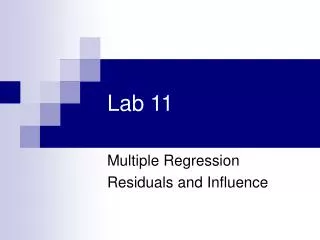
Voltage Input +5 VDC 4.7 K Xilinx XC95108 Interface VCC CS 1 8 Analog-to-Digital Converter ADC0831 VIN (+) CLK 7 2 VIN (-) DO 3 6 220 K VREF GND 4 5 Analog-to-Digital Converter Circuit
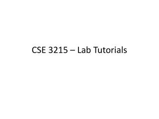
Clock 4.0 MHz Q0 Q1 Q2 0.5 MHz Q3 0.25 MHz The max. clock speed of the ADC0831 chip is 400 Khz, so we need a 4-bit counter to divide the PLDT-3 board 4 MHz clock frequency by 16. 2.0 MHz 1.0 MHz By extending this counter to eight bits, additional Analog-to-Digital Converter control signals can be generated.
Voltage Input +5 VDC 4.7 K Xilinx XC95108 Interface VCC CS 1 8 Analog-to-Digital Converter ADC0831 VIN (+) CLK 7 2 VIN (-) DO 3 6 220 K VREF GND 4 5 Analog-to-Digital Converter Circuit
Q3 Q4 Q5 Q6 Q7 Q3 (CLK) Q6 & Q7 (CS) Data Out (DO) 7 6 5 4 3 2 1 0
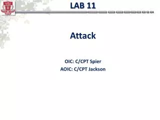
4 MHz Clock Xilinx XC95108 PC84 CPLD Clock Divider Counter Q7..Q0 Q3 CLK Q7 Q6 CS ADC0831 Interface DO
Q3 Q4 Q5 Q6 Q7 Q3 (CLK) Q6 & Q7 (CS) Data Out (DO) 7 6 5 4 3 2 1 0 !Q3 shift (S) 7 6 5 4 3 2 1 0 (Capture) [Q7..Q4] == 10 !Q3 display (D)
4 MHz Clock Xilinx XC95108 PC84 CPLD Clock Divider Counter Q7..Q0 Q3 CLK Q7 Q6 CS ADC0831 Interface Count Detect Logic (Q7..Q4 = 10102) Q3 !Q3 Clock Capture Shift Register S7..S0 Data DO Display Register D7..D0 Load Clock
Xilinx XC95108 PC84 CPLD (Shift Register S7..S0) (!Q3) (Capture) Display Register D7..D0 Load Clock Binary-to-BCD Converter Hundreds Tens Units 1 7-Segment Decoder 7-Segment Decoder 7 7 a..g a..g dpt Voltage Display 0 0
Pre-Lab: • Make a copy of your Bin9BCD.abl program from Group Homework # 5. • Make copies of your cadd3.abl, hex7seg.abl, and reg4bitg.abl from Labs 3 and 10. • Download a copy of the div16cnt.abl program from the class website. • Write an ABEL program, VM.abl, that provides the control signals for an ADC0831 chip and collects and displays the value of the measured voltage.
Lab: • Create a new project, Lab9a, and add a copy of your Bin9BCD.abl program. Simulate the Bin9BCD.abl program and print out a copy of the simulation report • Create a new project, Lab9b, and add a copy of your VM.abl program and copies of all embedded modules. • Generate a program file for your VM.abl program. • Build the ADC circuit on the breadboard and connect the circuit to the Xilinx XC95108 PC84 chip. Configure the PLDT-3 board and connect power to the PLDT-3 board. • Download and test your program. • Demonstrate your completed circuit to your lab instructor.