Download
1 / 18
180 likes | 333 Views
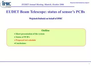
EUDET Beam Telescope: status of sensor’s PCBs. Wojciech Dulinski on behalf of IPHC. Outline Short presentation of the system Status of PCB’s Proposed test schedule Conclusions. Strasbourg MicroTelescope: a simplified version of EUDET telescope…. 4 reference planes DUT

E N D
EUDET Beam Telescope: status of sensor’s PCBs Wojciech Dulinski on behalf of IPHC • Outline • Short presentation of the system • Status of PCB’s • Proposed test schedule • Conclusions
Strasbourg MicroTelescope: a simplified version of EUDET telescope… • 4 reference planes • DUT • Si trigger plane • Ltot = 10 cm
Telescope PCBs and cables Beam area Control room Trigger PCB USB PP MimoTel (or HRTracker) on proximity PCB Auxiliary PCB Clock Tree Clock Root
MimoTel (Mimo*3M) and HR-Tracker (Mimosa18) proximity PCBs • Only passive components (mainly capacitors), except for first buffering of analog signals • Allows for precision alignment on the telescope mechanics (marks for chip gluing, holes for precision pins)
MimoTel (Mimo*3M) and HR-Tracker (Mimosa18) auxiliary PCB • Second buffering of analog signals (unipolar-differential) • Buffering of digital signals LVDS/CMOS, LVDS/LVDS, CMOS/LVDS • Power supply regulators • RJ45 connectors for analog and digital signals to external world • Flat cable connector (ERNI 50p) for proximity boards
Distribution of the clock and the JTAG(“Clock Tree”) • Second buffering of analog signals (unipolar-differential) • Buffering of digital signals LVDS/CMOS, LVDS/LVDS, CMOS/LVDS • Power supply regulators • RJ45 connectors for analog and digital signals to external world • Flat cable connector (ERNI 50p) for proximity boards
Assembling of the clock and the JTAG(“Clock Root”)First version: development board • Translation PC-ParallelPort LVDS for JTAG • Interconnection and buffering of fast digital signals (sensor clock, syncro, ADC clock…) • RJ45 connectors compatible with that on the Clock Tree board
PCB’s for EUDET: first setCurrent status: 5 sets assembled and tested, 15 sets to be assembled at DESY • One set of PCB’s contain: • Proximity board for Mimo*3M (MimoTEL): • Proximity board for HiRes Tracker • Auxiliary board for MimoTEL
PCB’s for EUDET: second setCurrent status: 5 sets in production, shall be assembled at Strasbourg in November • One set of PCB’s contain: • Clock and JTAG distribution (“Clock Tree”) • Clock and JTAG assembling (“Clock Root”)
AMS 0.35 µm OPTO engineering run submission (June/July 2006)Current status: ready, delivery in this days • Structures of direct interest for EUDET • Mimo*3M (MimoTEL): 256x256 pixels, 30µm pitch, 1KHz frame rate • High Resolution Tracker: 512x512 pixels, 10 µm pitch, 300 Hz frame rate • Mimosa16, the second prototype with a binary readout: 128x24 pixels, 25 µm pitch, on-chip column-level discriminator • ADC: 5 bits • TS1819: on-pixel amplifiers & clamping circuits Two types of wafers with epitaxy layer thickness of 14 µm and 20 µm are used Final layout of the reticle
Wafers delivery schedule • Firs wafer (14 µm epi) to be used for yield study (Mimo*L) at the probe station • Second wafer (20 µm epi) is cut at CMP and individual chips (non-thinned) ready to be used • There is an open option for the purchase of four remaining wafers, if the first test results positive…
Sensors test status/schedule Mimosa9 beam tests spatial resolution, after recent data re-analysis: Spatial resolution @30 µm pitch: 2 µm
High-precision tracker tests • Few proximity boards with bonded chips should be available in October. Other system components (auxiliary board, DAQ) available and used already in the past for Mimosa15 tests. • Detailed laboratory test results (calibration using Fe55 source) of at least one prototype expected before the end of 2006 • Beam test shall follow, schedule to be defined
Mimo*3M (MimoTEL) tests schedule(at Strasbourg) • Chips available from mid-October on • Proximity boards populated and chips bonded before the end of this year • JTAG programming model expected mid-January • Test results expected before March 2007
Mimosa16 tests schedule • Chips available before end of October • Bonding PCB (relatively simple, daughter card for existing Mimosa8 Proximity PCB) designed and fabricated (?) • Tests of analog part shall start at DAPNIA soon after bonding, using existing Mimosa8 set-up • Laboratory tests of digital part expected to start at Strasbourg from March on • Beam test in second half of 2007?
Implementation plans: phase 2 (“the ultimate device”) • Serious discussion of the schedule and intermediate milestones should happen during this meeting • Shall we foresee one intermediate step more, i.e. full size, fast, binary readout chip? I believe yes; such a chip will be very useful for testing of almost all building blocks of ILC detector, except for very high precision sensors
Conclusions Sensor production and delivery follows the original schedule. All demonstrator components shall be easily available several months before June 2007.For the second stage (digital readout sensor) the preparatory work (see Marc’s talk) is progressing. The detailed planning should be discussed soon
Appendix: latch-up test structure Simple circuit: four shift registers with slightly different digital cell layoutEach shift has its own power supplyThe goal is to measure latch-up cross section versus LET (Linear Energy Transfer, or dE/dx)Possible place (in Europe): Louvain (Belgium) or Jyvaskyla (Finland)