Download
1 / 33
330 likes | 528 Views
The Status of VIRGO E. Tournefier for the Virgo Collaboration GWADW 2004, Aspen. From the CITF to VIRGO Commissioning of the Fabry-Perot cavities Next steps. The CITF. E0 (September 2001). Displacement sensitivity (m/ Hz). E1. E2. E3. E4 (July 2002). E4 Shot noise.

E N D
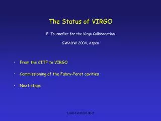
The Status of VIRGO E. Tournefier for the Virgo CollaborationGWADW 2004, Aspen • From the CITF to VIRGO • Commissioning of the Fabry-Perot cavities • Next steps LIGO-G040226-00-Z
The CITF LIGO-G040226-00-Z
E0 (September 2001) Displacementsensitivity(m/Hz) E1 E2 E3 E4 (July 2002) E4 Shot noise CITF design s. noise Virgo Frequency(Hz) The CITF commissioning • June 01-July 02: Central ITF (CITF) commissioning -> 5 engineering runs E0, E1: Michelson E2, E3, E4: Recycled Michelson LIGO-G040226-00-Z
From the CITF to VIRGO: upgrades A lot of experience gained with the CITF Problems detected -> several improvements have been prepared for VIRGO Aug 02: Shutdown for the Virgo installation and upgrades • Install the Virgo mirrors • Connect the tubes and install the terminal towers • Change beam size, modulation frequency • Upgrade the Input mode cleaner • Upgrade the control of the suspensions • Jul 03: end of installation • Aug 03: start the commissioning LIGO-G040226-00-Z
The first VIRGO mirror The Mirrors • Coater VIRGO in a class 1 clean room, unique in the world (2.2*2.2*2.4 m) • Coating features: • very low losses: scattering ~ 5 ppm, absorption ~ 1 ppm • Uniformity on large dimension: less than 10-3 variation on 350 mm Assembly of the NI mirror LIGO-G040226-00-Z
The mirror suspensions The superattenuator is expected to provide an attenuation of 1014 at 10 Hz 3 actuation points: • Inertial damping of the Inverted Pendulum • Local control of the marionnetta • Damping of the mirror motion LIGO-G040226-00-Z
Inverted pendulum motion on 24 hrs • Control of the top stage: • Horizontal damping using Lvdt’s and accelerometers • (improved to reduce re-introduction of noise by Lvdt’s) • Typical rms horizontal displacement of the top stage: 1m LIGO-G040226-00-Z
Vertical elongation of PR suspension No control Air cond improved vertical control • Control of the vertical motion: • Important for Power Recycling mirror: it acts as a lens • Vertical control using Lvdt (new) LIGO-G040226-00-Z
Force applied to mirror No feedback to top stage 3.5 mN with feedback to top stage • Tide control from the top stage: • Tide control tested on CITF, to be implemented for Virgo: • reallocate the locking force from the mirror to the top stage • -> smaller force on mirror -> lower noise from actuator LIGO-G040226-00-Z
Marionetta Laser diode Mirror PSD Local control of the Marionetta and of the mirror: - laser diode coupled to a camera or a PSD device: new on the Marionetta • The angular readout is done from the marionetta (new) and the mirror • The correction is sent to the marionetta -> typical rms angular motion of the mirror: 1 rad (see E. Majorana’s talk) LIGO-G040226-00-Z
The injection system Upgrades: • Change laser: 10W -> 20 W • Move the Mode Cleaner tower • Suspend the mode cleaner mirror and install its local controls LIGO-G040226-00-Z
The detection system • Upgrade of the photodiodes electronics for the new modulation frequency (6.25 MHz) • Upgrade of the optical system for the VIRGO beam size • Add of Faraday isolator after the output mode cleaner • Add the readout of the bad polarisation The suspended detection bench Output mode cleaner filtering the dark fringe LIGO-G040226-00-Z
Displacement induced by 1,2W laser CITF The optical calibrator Calibration needed to transform photodiode signal into real mirror displacement Mirror displaced by radiation pressure (1.2W laser diode) Need to have a good sensitivity before this system can be used => use mirror coils now (like for CITF) Virgo LIGO-G040226-00-Z
Phases of the commissioning • Aug-Oct 03: alignment of the injection beam, the Beam Splitter, the FP cavities, and the detection bench LIGO-G040226-00-Z
Phases of the commissioning • Aug-Oct 03: alignment of the injection beam, the Beam Splitter, the FP cavities, and the detection bench • Since Oct 03: North FP cavity commissioning LIGO-G040226-00-Z
Phases of the commissioning • Aug-Oct 03: alignment of the injection beam, the Beam Splitter, the FP cavities, and the detection bench • Since Oct 03: North FP cavity commissioning • Dec03: start West FP cavity commissioning LIGO-G040226-00-Z
Phases of the commissioning • Aug-Oct 03: alignment of the injection beam, the Beam Splitter, the FP cavities, and the detection bench • Since Oct 03: North FP cavity commissioning • Dec03: start West FP cavity commissioning • March 04: start Recombined Michelson commissioning LIGO-G040226-00-Z
North FP cavity locking • Alignment of the cavity • Confront photodiode signals with simulation (SIESTA) simulation reality LIGO-G040226-00-Z
DC AC/DC AC Lock of the FP cavity • Use the linearized error signal: AC/DC DC Power stored in the cavity Error signal • Time to act is increased by a factor 10 with the linearised signal • Force on mirror reduced LIGO-G040226-00-Z
Lock of the FP cavity • Oct 28th: first lock of the North FP cavity Power fluctuations due to: - laser frequency noise (high freq) - angular motion of the mirrors (low freq) • Reduce laser frequency noise • Implement automatic alignment of the mirrors The lock of the FP cavities is almost always acquired at first attempt thanks to the low speed of the mirrors: ~2 m/sec LIGO-G040226-00-Z
Lock of the Output mode cleaner AC power spectrum • Once the cavity is locked: • Lock the output mode cleaner • Control the cavity with the OMC output signal -> improves the sensitivity at high frequencies LIGO-G040226-00-Z
First commissioning run: C1 3 days (november 14-17): • North FP cavity locked with linearised signal • Output mode cleaner locked Power stored in the cavity(a.u) re-alignment network failure operation large seismic noise ( sea storm) Alaska earthquake test Suspension point displacement (m) LIGO-G040226-00-Z
calib z correction O [m] G H Calibration Reconstruction of the sensitivity from the photodiode signal: -> Measurement of the closed loop transfert function with white noise (injected from mirror coils) Closed loop TF LIGO-G040226-00-Z
Angular noise Frequency noise Electronic noise (ADC) C1 sensitivity LIGO-G040226-00-Z
C1 run outcomes - in normal conditions the lock of the cavity is very stable - injection system stable: only 1 loss of lock (due to the earthquake) - sensitive to large seismic noise -> the inertial damping has been improved - many realignments needed -> the automatic alignment is being implemented - the sensitivity is limited by laser frequency noise -> improve injection control -> implement the second stage frequency stabilization - an acoustic test in the laser lab showed that a lot of the frequency noise is induced by acoustic noise -> improve the isolation LIGO-G040226-00-Z
C1 run 15 Jan Seismometers Top stage displacement Sensitivity to large seismic noise • The top stage Inertial Damping uses LVDTs (low frequency) and accelerometers • Seismic noise is reintroduced by LVDTs -> new filter has been designed to reduce this effect (see E. Majorana’s talk) => Now implemented on all the towers and works well LIGO-G040226-00-Z
Injection system control • Input bench and mode cleaner damped with respect to the ground • Laser frequency locked to mode cleaner length LIGO-G040226-00-Z
Noise Environmental noise introduced through the automatic alignment Readout noise introduced through MC length control Noise Injection system control • Input bench and mode cleaner damped with respect to the ground • Laser frequency locked to mode cleaner length • Mode cleaner length locked to reference cavity • Mode cleaner mirror automatically aligned to input beam LIGO-G040226-00-Z
C1 sensitivity Environmental noise ITF signal (a.u.) C1 Frequency noise hypothesis now MC length control noise hypothesis Improvement of the controls of the injection • Automatic alignment control gains reduced -> less sensitive to environmental noise • MC control length bandwidth reduced -> less noise injected at high frequency LIGO-G040226-00-Z
Next steps • The linear automatic alignment is implemented and under test: Angular control of the cavity mirrors using signals of quadrant photodiodes -> reduce the power fluctuations at low frequency • Implement the laser frequency stabilization • Study the mirrors hierachical control: lock from the marionetta in order to reduce the force on the mirror ( and therefore the noise) • And start the commissioning of the recombined Michelson LIGO-G040226-00-Z
Conclusion • Summer 2003: End of the Virgo sub-systems upgrade • Since autumn 2003: Commissioning of Virgo - Commissioning of the two Fabry-Perot cavities • First run with one cavity • Now: • Implementing the laser frequency stabilisation • Prepare the commissioning of the recombined Michelson • Next run: end of this week (feb 19-22) with the 2 FP cavities • Futur: • Recombined Michelson: spring 2004 • Recycled Michelson: end 2004 • first scientific run: 2005 ? LIGO-G040226-00-Z
Monday morning earthquake • Earthquake happened in the Rat Island (Alaska) Nov/17 at 06:43:07 UTC: • magnitude 7.3 Richter • Travel time to Virgo is approx. 1hour • Peak frequency of the seismic wave at Virgo is approx. 0.70mHz Top stage displacement • Earthquake trigger the inertial damping security system of the injection bench suspension • loop was open and input mode-cleaner unlocked LIGO-G040226-00-Z
GC DSP DSP Ref Cav laser D1p electronics IMC Analog elec. • Second stage of laser frequency stabilisation LIGO-G040226-00-Z