MicroLogix Programmable Controller Basics and Files
Explore program files, concepts, and memory organization for MicroLogix 1000 Packaged Controllers. Learn about I/O addressing, logic, and examples. Understand the dedicated files for system, main program, errors, and more. Discover the essentials of relay ladder logic and its graphical representation.

MicroLogix Programmable Controller Basics and Files
E N D
Presentation Transcript
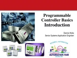
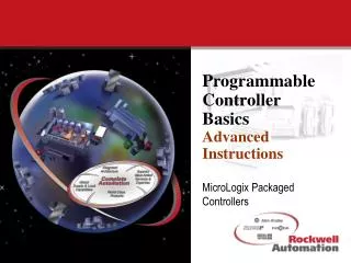
Programmable Controller BasicsFiles And Programs MicroLogix Packaged Controllers
We are going to discuss... 1. What Are Program Files 2. Program File Functions 3. Ladder Logic Concepts 4. I/O Addressing 5. Logic 6. Examples
DATA FILES 0 1 2 Output File Input File 3 4 Status File Bit File 5 6 Timer File 7 Counter File Control File Integer Files PROGRAM FILES 0 1 2 System 3 Reserved 4 5 Main Program Error File 6 - 15 HSC File STI File Subroutine Files Memory Organization MicroLogix 1000 MEMORY MicroLogix 1000 only
PROGRAM FILES 0 1 2 System 3 Reserved 4 5 Main Program 6 - 15 Error File HSC File STI File Subroutine Files Memory Organization MicroLogix 1000 MEMORY MicroLogix 1000 only
File 0 - System File Dedicated & Reserved file • Used to store various system related information. • Processor type and configuration • Communication parameters • I/O configuration • Passwords • Misc...
File 1 - Reserved • Future • New enhancements • New features • New functionality
File 2 - Main Program Dedicated & Open file • Main Ladder Program • Typically is where the “main” user program resides • Must have some program logic
File 3 - Error File Preconfigured and Open file • Referred to as the Error Subroutine • Will be “scanned” whenever a recoverable fault is detected(Allows users to clear certain errors and inhibit a shutdown) • Recoverable faults include: • Retentive data lost (0005) • Startup protection after power loss (0016) • Minor Error at end of scan (0020) • File boundaries violated ( Sequencers 0032, Stacks and Bit Shifts (0033) • Negative data in ACC or PRE of a timer (0034) • Invalid HSC preset (0037) • May be used as a user subroutine, but is not recommended
File 4 - High Speed Counter File Preconfigured and Open file • Referred to as the HSC Subroutine • Will be “scanned” whenever a HSC interrupt occurs • HSC Interrupts are: • “Preset” data value is reached (High or Low) • Underflow or Overflow conditions are detected • May be used as a user subroutine, but is not recommended
File 5 - Selectable Timed Interrupt File Preconfigured and Open file • Referred to as the STI subroutine • Scanned whenever the STE instruction is set (1) • Adjustable interval, 10msec resolution • May be used as a user subroutine, but is not recommended
Files 6-15 - User Subroutines “Open” Files • Typically used for application specific requirements. • Accessed from file 2 (Main program) through special program flow instructions • JSR Jump to Subroutine and return • SBR Subroutine Identifier • RET Ret to Main program • Nesting of subroutines is allowed(8 Levels allowed, 3 Levels if the Error, HSC or STI subroutines are enabled) • MicroLogix 1000 and SLC 500 only
Relay Ladder Logic (RLL) • What is Relay Ladder Logic? • Is the primary programming language for PLCs • A graphical representation of the program designed to look like relay logic
( ) ( ) ( ) ( ) Ladder Logic Concepts Read / Conditional Instructions Write / Control Instructions | | Start (Rung #1) | | |/| | | |/| | | | | |/| | | | | |/| ( ) End (Rung #5)
( ) ( ) Ladder Logic Concepts Read / Conditional Instructions Write / Control Instructions |/| | | F T F No Logical Continuity |/| |/| T T T Logical Continuity
I/4 I/5 O/0 | | | | ( ) Logical AND Construction IF input 4AND input 5 have power THEN energize output 0 On T T T Logical Continuity
I/4 O/0 | | ( ) I/5 | | I/4 O/0 | | ( ) I/5 | | Logical OR Construction IF input 4OR input 5 have power THEN energize output 0 T On Logical Continuity F F On Logical Continuity T
I/4 I/0 I/1 I/9 O/0 |/| | | | | | | ( ) I/5 I/1 I/7 I/8 | | |/| |/| |/| I/2 I/3 | | | | I/1 | | Complex Construction I/10 | | I/11 |/|
Read Instructions The instruction is: If the input device is The input bit is Examine OFF -|/|- XIO Examine ON -| |- XIC False True Open (0) Logic 0 True False Closed (1) Logic 1
| | |/| ( ) T T T Write Instruction Rung State Output Terminal Output Bit ON ENERGIZED OTE Output Energize -( )- TRUE FALSE OFF De-energized
Supply Voltage Putting it Together PB1 Unused Unused COM I / 0 I / 1 I / 2 I / 3 I / 4 COM I / 5 I / 6 I / 7 I / 8 I / 9 L 1 L 2 / N GND VAC O / 0 VAC O / 1 VAC O / 2 VAC O / 3 VAC O / 4 O / 5 VDC VDC VDC VDC VDC Supply Voltage O/0 I/8 | | ( )
SOL6 LS1 PS2 ADDRESS HHP I/5 I/6 I/7 O/0 Logix I:0/5 I:0/6 I:0/7 O:0/0 Addressing Example L1 L2 PB1 O/0 I/6 I/7 I/5 | | | | | | ( ) DEVICE PB1 LS1 PS2 SOL6
SOL2 PB1 LS1 I/4 I/6 O/0 PB2 LS1 CR3 | | | | ( ) LS3 I/7 I/5 B/0 | | | | ( ) M1 LS4 CR3 | | B/0 |/| |/| O/1 ( ) Relay Logic to Ladder Logic I/8 I/9 | | INPUT Address Assignment: PB1- I/4 PB2- I/5 LS1- I/6 LS2- I/7 LS3- I/8 LS4- I/9 OUTPUT Address Assignment: SOL2- O/0 M1- O/1