
Object Oriented Analysis
E N D
Presentation Transcript
Object Oriented Analysis Chapter Two
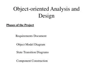
Introduction OOA Consists of- • Requirement (basic user requirement) analysis. • Identification of classes and its hierarchy. • Representation of object-to-object relationships. • Modeling of object behaviors. • The steps are repeated until model is completed. Objective of OOA is to develop a model that describes computer software as it works to satisfy a set of customer-defined requirements.
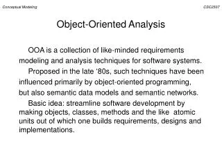
Introduction Cont.. • A domain model is a visual representation of conceptual classes or real-situation objects in a domain. • Domain models have also been called conceptual models, domain object models, and analysis object models.
Why Call a Domain Model a "Visual Dictionary”? • Please reflect on Figure 2 for a moment. See how it visualizes and relates words or concepts in the domain. It also shows an abstraction of the conceptual classes, because there are many other things one could communicate about registers, sales, and so forth. The information it illustrates (using UML notation) could alternatively have been expressed in plain text (in the UP(Unified Process) Glossary). But it's easy to understand the terms and especially their relationships in a visual language, since our brains are good at understanding visual elements and line connections. Therefore, the domain model is a visual dictionary of the noteworthy abstractions, domain vocabulary, and information content of the domain.
Why Create a Domain Model? • Lower Representational Gap with OO Modeling. • For example, here's a source-code payroll program written in 1953: 1000010101000111101010101010001010101010101111010101 …
Conceptual Modeling: • A domain model shows the real world conceptual classes – not the software classes. • The domain objects required for the modeling are obtained from the decomposition of the domain of the interest. • It is a visual representation of real world objects in the domain hence sometimes called domain objects model. • The UML notation illustrates a set of class diagrams without operations but showing domain objects, their association and attributes. • Key ideas of domain model are: • Domain model is a visual dictionary of abstractions. • Domain models are not models of software components.
Conceptual Classes • They are either an idea or thing or an object, identified as a result of different level of abstraction of the domain. • They have three parts: • Symbol: Usually represented by a rectangle. • Intension: The definition of the class. • Extension: It is object instances of the classes.
Conceptual Class identification • A domain model is built incrementally over a number of iterations in the elaboration phase. • In each build, all possible conceptual classes and relationships of the current scenarios are added to the prior model. • The central task is to identify the domain objects related to the scenario.
Guideline • Try to identify as much of the conceptual classes as possible. • Do not worry about missing some of the conceptual classes but make sure that they will be incorporated later when they are identified in the process of identifying attributes and association among domain classes. • Also include in the model with those conceptual classes that are not indicated clearly by the requirements. • Classes not having attributes or having only behavioral role can also be taken as a conceptual class.
How to make a domain model? • Prepare the conceptual class category list • Use Noun phrase identification technique • Draw these objects in a domain model • Add necessary associations • Add required attributes
Adding associations to Domain Model • An association is a semantic relationship between things, concepts or ideas. It represents meaningful connections. • Terminology in association: Role, Association Name, Multiplicity. • Useful Associations • Need-to-know associations: relationship that are to be preserved for later use. • Associations derived from the common association list • -High priority associations • A is a physical or logical part of B • A is physically or logically contained in B • A is recorded in B.
Multiple Associations • More than one association can exist between two or more classes. • Implementation of Associations: • It is more important to identify conceptual classes that has associations at the elaboration phase. • Some associations of domain model may not be required to be implemented. • Some associations might be discovered at the time of implementation only and the domain model should have to be changed to reflect these discoveries.
How to Create a Domain Model? • Find the conceptual classes. • Draw them as classes in a UML class diagram. • Add associations and attributes.
How to Find Conceptual Classes? • Reuse or modify existing models. This is the first, best, and usually easiest approach, and where I will start if I can. There are published, well-crafted domain models and data models (which can be modified into domain models) for many common domains, such as inventory, finance, health, and so forth. • Use a category list. • Identify noun phrases.
Finding Conceptual Classes with Noun Phrase Identification Main Success Scenario (or Basic Flow): • Customer arrives at a POS checkout with goods and/or services to purchase. • Cashier starts a new sale. • Cashier enters item identifier. • System records sale line item and presents item description, price, and running total. Price calculated from a set of price rules. Cashier repeats steps 2-3 until indicates done. • System presents total with taxes calculated. • Cashier tells Customer the total, and asks for payment. • Customer pays and System handles payment. • System logs the completed sale and sends sale and payment information to the external Accounting (for accounting and commissions) and Inventory systems (to updateinventory). • System presents receipt. • Customer leaves with receipt and goods (if any).
A Common Mistake with Attributes vs. Classes • If we do not think of some conceptual class X as a number or text in the real world, X is probably a conceptual class, not an attribute. (Class may be a massive thing that occupies space). • Example: • Should “store” be an attribute of “Sale” or a separate conceptual class Store?
Why Use 'Description' Classes? • Switching from a conceptual to a software perspective, even if all inventoried items are sold and corresponding instances are deleted, the ProductDescription still remains. • See at next page.
Cont.. • Descriptions about other things. The * means a multiplicity of "many." • It indicates that one ProductDescription may describe many (*) Items.
When Are Description Classes Useful? • Add a description class (for example, ProductDescription) when: • There needs to be a description about an item or service, independent of the current existence of any examples of those items or services. • Deleting instances of things they describe (for example, Item) results in a loss of information that needs to be maintained, but was incorrectly associated with the deleted thing. • It reduces redundant or duplicated information.
Adding Associations and Attributes Adding Associations • An optional "reading direction arrow" indicates the direction to read the association name; it does not indicate direction of visibility or navigation. • If the arrow is not present, the convention is to read the association from left to right or top to bottom, although the UML does not make this a rule. See figure below • Note: The reading direction arrow has no meaning in terms of the model; it is only an aid to thereader of the diagram.
An association is a relationship between classes, that indicates some meaningful and interesting connection. • Consider including the following associations in a domain model: • Associations for which knowledge of the relationship needs to be preserved for some duration. • Associations derived from the Common Associations List.
Cont.. • The "reading direction arrow" indicates the direction to read the association name; it does not indicate direction of visibility or navigation. • If the arrow is not present, the convention is to read the association from left to right or top to bottom, although the UML does not make this a rule.
Cont.. • Name as association based on ClassName-VerbPhrase-ClassName format. • Simple association names such as “has”, “uses” are used. • Multiplicity defines how many instances of class A can be associated with one instance of class B. • Multiplicity in context dependent.
Roles • Each end of an association is called a role. • Roles may optionally have: • multiplicity expression • name • Navigability
Cont.. • For example, a single instance of a Store can be associated with "many" (zero or more, indicated by the *) Item instances.
Attributes • An attribute is a logical data value of an object. • Notation- • visibility name : type multiplicity = default {property-string}
Attributes • The total attribute in the Sale can be calculated or derived from the information in the SalesLineItems. Denoted by “/” symbol.
Relate conceptual classes with an association, not with an attribute.
Class Work • Example-2: Domain model of “Buy a Product Scenario”. • A web-based online store has Buy a Product scenario as follows: “The customer browses a catalog and adds desired items to the shopping basket. When the customer wishes to pay, the customer describes the shipping and credit card information and confirms the sale. The system checks the authorization on the credit card and confirms the sale both immediately and with a follow-up e-mail.”
Representations of System Behavior • System behavior is a description ofwhata system does, without explaining how it does. • Onepart of that description is a system sequence diagram. Other parts include the use cases and system operation contracts. • System behavior can be represented by using following: • Use cases • System Sequence diagrams, Collaboration diagrams • Operation contracts
System Sequence Diagram (SSD) • A system sequence diagram is a picture that shows, for one particular scenario of a use case, the events that external actors generate, their order, and inter-system events. • All systems are treated as a black box. • The emphasis of the diagram is events that cross the system boundary from actors to systems • Draw an SSD for a main success scenario of each use case, and frequent or complex alternative scenarios.
Drawing an SSD From Use case • Draw System as black box on right side. • For each actor that directly operates on the System, draw a stick figure and a lifeline. • For each System events that each actor generates in use case, draw a message. • Optionally, include use case text to left of diagram.
Let us Re-visit Main Success Scenario (or Basic Flow): • Customer arrives at a POS checkout with goods and/or services to purchase. • Cashier starts a new sale. • Cashier enters item identifier. • System records sale line item and presents item description, price, and running total. Price calculated from a set of price rules. Cashier repeats steps 2-3 until indicates done. • System presents total with taxes calculated. • Cashier tells Customer the total, and asks for payment. • Customer pays and System handles payment. • System logs the completed sale and sends sale and payment information to the external Accounting (for accounting and commissions) and Inventory systems (to updateinventory). • System presents receipt. • Customer leaves with receipt and goods (if any).
Figure : SSDs are derived from use cases; they show one scenario.