Download
1 / 52
660 likes | 1.47k Views
Gaseous Fuels. 朱信 Hsin Chu Professor Dept. of Environmental Engineering National Cheng Kung University. 1. Introduction. There are numerous factors which need to be taken into account when selecting a fuel for any give application.

E N D
Gaseous Fuels 朱信 Hsin Chu Professor Dept. of Environmental Engineering National Cheng Kung University
1. Introduction • There are numerous factors which need to be taken into account when selecting a fuel for any give application. • Economics is the overriding consideration-the capital cost of the combustion equipment together with the running costs, which are fuel purchasing and maintenance.
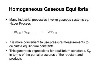
2. Natural Gas • Natural gas is obtained from deposits in sedimentary rock formations which are also sources of oil. • It is extracted from production fields and piped (at approximately 90 bar) to a processing plant where condensable hydrocarbons are extracted from the raw product.
It is then distributed in a high-pressure mains system. • Pressure losses are made up by intermediate booster stations and the pressure is dropped to around 2500 Pa in governor installations where gas is taken from the mains and enters local distribution networks.
The initial processing, compression and heating at governor installations uses the gas as an energy source. • The energy overhead of the winning and distribution of a natural gas is about 6% of the extracted calorific value.
The composition of a natural gas will vary according to where it was extracted from, but the principal constituent is always methane. • There are generally small quantities of higher hydrocarbons together with around 1% by volume of inert gas (mostly nitrogen).
The characteristics of a typical natural gas are:Composition (% vol) CH4 92 other HC 5 inert gases 3Density (kg/m3) 0.7Gross calorific value (MJ/m3) 41
3. Town gas (Coal Gas) • The original source of the gas which was distributed to towns and cities by supply utilities was from the gasification of coal. • The process consisted of burning a suitable grade of coal in a bed with a carefully controlled air supply (and steam injection) to produce gas and also coke.
This is still the gas supplied by utility companies in many parts of the world (e.g. Hong Kong) and there is continuing longer-term development of coal gasification, since it is one of the most likely ways of exploiting the substantial world reserves of solid fuel. • It was first introduced into the UK and the USA at the beginning of the 19th century.
The gas was produced by heating the raw coal in the absence of air to drive off the volatile products. • This was essentially a two-stage process, with the carbon in the coal being initially oxidized to carbon dioxide, followed by a reduction to carbon monoxide: C + O2→ CO2 CO2 + C → 2CO
The volatile constituents from the coal were also present, hence the gas contained some methane and hydrogen from this source. • An improved product was obtained if water was admitted to the reacting mixture, the water being reduced in the so-called water gas shift reaction: C + H2O → CO + H2
This gas was produced by a cyclic process where the reacting bed was alternately blown with air and steam- the former exhibiting an exothermic, and the latter an endothermic, reaction. • A typical town gas produced by this process has the following properties:Composition (% vol) H2 48 CO 5 CH4 34 CO2 13Density (kg/m3) 0.6Gross calorific value (MJ/m3) 20.2
A more recent gasification process, developed since 1936, is the Lurgi gasifier. • In this process the reaction vessel is pressurized, and oxygen (as opposed to air) as well as steam is injected into the hot bed. • The products of this stage of the reaction are principally carbon monoxide and hydrogen.
Further reaction to methane is promoted by a nickel catalyst at temperatures of about 250-350℃: CO + 3H2→ CH4+ H2O • The sulfur present in the coal can be removed by the presence of limestone as follows: H2 + S → H2S H2S + CaCO3→ CaS +H2O +CO2
4. Liquefied Petroleum Gas (LPG) • LPG is a petroleum-derived product distributed and stored as a liquid in pressurized containers. • LPG fuels have slightly variable properties, but they are generally based on propane (C3H8) or the less volatile butane (C4H10).
Compared to the gaseous fuel described above, commercial propane and butane have higher calorific values (on a volumetric basis) and higher densities. • Both these fuels are heavier than air, which can have a bearing on safety precautions in some circumstances.
Typical properties of industrial LPG are given below:Gas Propane Butane Density (kg/m3) 1.7-1.9 2.3-2.5 Gross calorific value (MJ/m3) 96 122 Boiling point (℃ at 1 bar) -45 0
5. Combustion of Gaseous Fuels 5.1 Flammability Limits • Gaseous fuels are capable of being fully mixed (i.e. at a molecular level) with the combustion air. • However, not all mixtures of fuel and air are capable of supporting, or propagating, a flame.
Imagine that a region of space containing a fuel/air mixture consists of many small discrete (control) volumes. • If an ignition source is applied to one of these small volumes, then a flame will propagate throughout the mixture if the energy transfer out of the control volume is sufficient to cause ignition in the adjacent regions.
Clearly the temperature generated in the control volume will be greatest if the mixture is stoichiometric, where as if the mixture goes progressively either fuel-rich or fuel-lean, the temperature will decrease. • When the energy transfer from the initial control volume is insufficient to propagate a flame, the mixture will be nonflammable.
This simplified picture indicates that there will be upper and lower flammability limits for any gaseous fuel, and that they will be approximately symmetrically distributed about the stoichiometric fuel/air ratio.
Flammability limits can be experimentally determined to a high degree of repeatability in an apparatus developed by the US Bureau of Mines. • The apparatus consists of a flame tube with ignition electrodes near to its lower end (Fig. 7.1, next slide).
Intimate mixing of the gas/air mixture is obtained by recirculating the mixture with a pump. • Once this has been achieved, the cover plate is removed and a spark is activated. • The mixture is considered flammable if a flame propagates upwards a minimum distance of 750 mm.
The limits are affected by temperature and pressure but the values are usually quoted as volume percentages at atmospheric pressure and 25℃. • Typical values for some gaseous fuels are:Fuel Lower Explosion Limit (LEL) % Upper Explosion Limit (UEL) %Methane 5 15Propane 2 10Hydrogen 4 74Carbon monoxide 13 74
5.2 Burning Velocity • The burning velocity of a gas-air mixture is the rate at which a flat flame front is propagated through its static medium, and it is an important parameter in the design of premixed burners. • A simple method of measuring the burning velocity is to establish a flame on the end of a tube similar to that of a laboratory Bunsen burner.
When burning is aerated mode, the flame has a distinctive bright blue cone sitting on the end of the tube. • The flame front on the gas mixture is travelling inwards normally to the surface of this cone (Fig. 7.2, next slide).
If U represents the mean velocity of the gas-air mixture at the end of the tube and α is the half-angle of the cone at the top of the tube, then the burning velocity S can be obtained simply from: S = U sin (α) • This method underestimates the value of S for a number of reasons, including the velocity distribution across the end of the tube and heat losses from the flame to the rim of the tube.
More accurate measurements are made with a burner design which produces a flat, laminar flame. • Some typical burning velocities are: Fuel Burning velocity (m/s) Methane 0.34 Propane 0.40 Town gas 1.0 Hydrogen 2.52 Carbon monoxide 0.43
Burning velocity should not be confused with the speed of propagation of the flame front relative to a fixed point, which is generally referred to as flame speed. • In this case, the speed of the flame front is accelerated by the expansion of the hot gas behind the flame.
5.3 Wobbe Number • This characteristic concerns the interchangeability of one gaseous fuel with another in the same equipment. • In very basic terms, a burner can be viewed in terms of the gas being supplied through a restricted orifice into a zone where ignition and combustion take place.
The three important variables affecting the performance of this system are the size of the orifice, the pressure across it (or the supply pressure if the combustion zone is at ambient pressure) and the calorific value of the fuel, which determines the heat release rate. • If two gaseous fuels are to be interchangeable, the same supply pressure should produce the same heat release rate.
If we consider the restriction to behave like a sharp-edged orifice plate, and if the cross-sectional area of the orifice (A0) is much less than the cross-sectional area of the supply pipe then the mass flow rate of fuel is given by: = CdA0 (2ρ△p)0.5or in terms of volume flow rate:where Cd is a discharge coefficientρ is the density of fuel
The heat release rate, Q, will be obtained by multiplying the volume flow rate by the volumetric calorific value of the fuel: • If we have two fuels denoted as 1 and 2, we would expect the same heat release from the same orifice and the same pressure drop △p, if
This ratio is known as the Wobbe number of a gaseous fuel and is defined as: • Some typical Wobbe numbers are: Fuel Wobbe number (MJ/m3) Methane 55 Propane 78 Natural gas 50 Town gas 27
The significant difference between the values for natural gas and town gas illustrates why appliance conversions were necessary when the UK changed its mains-distributed fuel in 1966. • Example 1:Calculate the Wobbe number for a by-product gas from an industrial process which has the following composition by volume: H2 12% CO 29% CH4 3% N2 52% CO2 4%
Solution:The gross calorific values are: CO 11.85 MJ/m3 CH4 37.07 MJ/m3 H2 11.92 MJ/m3 • The calorific value of the mixture:CV=(0.12×11.92)+(0.29×11.85)+(0.03×37.07)=5.98 MJ/m3
The relative density of the mixture is calculated by dividing the mean molecular weight of the gas by the corresponding value for air (28.84). • The mean molecular weight of this mixture is:(0.12×2)+(0.29×28)+(0.03×16)+(0.52×28)+(0.04×44)=25.16
The relative density is thus 25.16÷28.84=0.872. • The Wobbe number is then: 5.98/(0.872)0.5=6.36 • The Wobbe number of a fuel is not the only factor in determining the suitability of a fuel for a particular burner. • The burning velocity of a fuel is also important.
In general, any device will operate within a triangular performance map, such as that sketched in Fig. 7.3 (next slide). • Outside the enclosed region, combustion characteristics will be unsatisfactory in the way indicated on the diagram.
6. Gas Burners 6.1 Diffusion Burners • The fuel issues from a jet into the surrounding air and the flame burns by diffusion of this air into the gas envelope (Fig. 7.4, next slide).
A diffusion flame from a hydrocarbon fuel has a yellow color as a result of radiation from the carbon particles which are formed within the flame. • The flame can have laminar characteristics or it may be turbulent if the Reynolds number at the nozzle of the burner is greater than 2,000.
Pratical burner operate in the turbulent regime since more efficient combustion is obtained in this case because the turbulence improves the mixing of the fuel with air. • Industrial diffusion burners will have typical supply gas pressures of 110 Pa.
Diffusion burners have the following positive characteristics:(a) Quiet operation(b) High radiation heat transfer (about 20% of the total)(c) Will burn a wide range of gases (they cannot light back)(d) Useful for low calorific value fuels
6.2 Premixed Burners • The vast majority of practical gaseous burners mix the air and fuel before they pass through a jet into the combustion zone. • In the simplest burners, such as those that are used in domestic cookers and boilers, the buoyancy force generated by the hot gases is used to overcome the resistance of the equipment. • However, in larger installations the gas supply pressure is boosted and the air is supplied by a fan.
The principle is illustrated by the flame from a Bunsen burner with the air hole open, and is shown diagrammatically in Fig. 7.5 (next slide).The gas and air are mixed between the fuel jet and the burner jet, usually with all the air required for complete combustion.