Download
1 / 154
1.57k likes | 1.7k Views
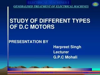
STUDY OF DIFFERENT TYPES OF D.C MOTORS PRESESNTATION BY Harpreet Singh Lecturer G.P.C Mohali. +. +. +. +. +. +. +. +. DC MACHINES. FIELD WINDING.

E N D
STUDY OF DIFFERENT TYPES OF D.C MOTORS PRESESNTATION BY Harpreet Singh Lecturer G.P.C Mohali
+ + + + . . . . + + + + DC MACHINES FIELD WINDING YOKE S BRUSH AXIS ARMATURE _ + + BRUSH ARMATURE CONDUCTORS FIELD POLES N MAIN FIELD AXIS APPLICATION CONCEPT OF ALIGNMENT OF TWO MAGNETIC FIELDS LECTURE 5 OF 40
DC MACHINES S ( GENERATOR ) A B _ S N MECHANICAL INPUT + Te Tm ELECTRICAL LOAD N APPLICATION CONCEPT OF ALIGNMENT OF TWO MAGNETIC FIELDS LECTURE 5 OF 40
DC MACHINES S ( MOTOR ) A B _ S N MECHANICAL LOAD + Te DC SUPPLY v TL N APPLICATION CONCEPT OF ALIGNMENT OF TWO MAGNETIC FIELDS LECTURE 5 OF 40
DC MACHINES Electrical machines can be classified mainly into DC Machines and AC Machines. Slide no 1 shows the view of a dc machine. For simplicity , only main component parts have been shown. APPLICATION CONCEPT OF ALIGNMENT OF TWO MAGNETIC FIELDS LECTURE 5 OF 40
DC MACHINES The field windings are shown as excited from external source.The polarity of electro-magnetic field will depend upon the direction of field current as shown in the fig. of slide no.1 . APPLICATION CONCEPT OF ALIGNMENT OF TWO MAGNETIC FIELDS LECTURE 5 OF 40
DC MACHINES The armature carries conductors in side the slots.Two brushes are placed at the right angle to the main field axis. The brushes are stationary whereas armature is free to rotate. APPLICATION CONCEPT OF ALIGNMENT OF TWO MAGNETIC FIELDS LECTURE 5 OF 40
DC MACHINES When the armature is rotated in the magnetic field, an e.m.f will be induced in the armature conductors.The direction of the induced e.m.f can be found by applying Fleming’s Right Hand Rule. APPLICATION CONCEPT OF ALIGNMENT OF TWO MAGNETIC FIELDS LECTURE 5 OF 40
DC MACHINES The direction of induced e.m.f will depend upon the direction of rotation of armature , if polarity of field poles to be kept unchanged.When load is connected across the armature terminals , the current will flow through the armature circuit. APPLICATION CONCEPT OF ALIGNMENT OF TWO MAGNETIC FIELDS LECTURE 5 OF 40
DC MACHINES The direction of current will be same as that of induced e.m.f. The armature will now be considered as electro-magnet and its polarity is shown in the fig. of slide no. 2 .The electro-magnetic torque Te will be developed in the anti-clock wise direction as shown in the fig.of slide no. 1 and 2. APPLICATION CONCEPT OF ALIGNMENT OF TWO MAGNETIC FIELDS LECTURE 5 OF 40
DC MACHINES The magnitude of Te will depend on the strength of the field poles and armature field which further depends upon the currents flowing through the respective windings. As the external load on the generator is increased, the magnitude of Te increases. APPLICATION CONCEPT OF ALIGNMENT OF TWO MAGNETIC FIELDS LECTURE 5 OF 40
DC MACHINES As Te acts in the opposite direction to the applied mechanical torque, more torque will be required through the prime mover to maintain the speed of armature . APPLICATION CONCEPT OF ALIGNMENT OF TWO MAGNETIC FIELDS LECTURE 5 OF 40
DC MACHINES The direction of currents in the upper conductors in the armature are indicated by ‘dots’ and conductors in lower half of armature are indicated by ‘cross’ . APPLICATION CONCEPT OF ALIGNMENT OF TWO MAGNETIC FIELDS LECTURE 5 OF 40
DC MACHINES The brush ‘B’ will collect dot currents and brush ‘A’ will collect cross currents as the armature continues to rotate in clockwise direction. In the out put circuit, across terminals ‘A’ and ‘B’, current will flow in one direction. APPLICATION CONCEPT OF ALIGNMENT OF TWO MAGNETIC FIELDS LECTURE 5 OF 40
DC MACHINES The dc machine shown in fig. of slide no. 2 is working as generator.The same machine will work as motor , if the armature is provided with electric supply as shown in fig. of slide no. 3 . APPLICATION CONCEPT OF ALIGNMENT OF TWO MAGNETIC FIELDS LECTURE 5 OF 40
DC MACHINES The armature is connected across a supply voltage ‘V’ and the field windings are excited from the same supply or from any external dc source.The magnetic polarities due to the current in armature winding will be as shown in fig. of slide no. 3 . APPLICATION CONCEPT OF ALIGNMENT OF TWO MAGNETIC FIELDS LECTURE 5 OF 40
DC MACHINES The electro-magnetic torque Te will be developed in the anti-clockwise direction as opposite poles of armature field and main field will attract each other. The armature will rotate in anti-clockwise direction due to Te . APPLICATION CONCEPT OF ALIGNMENT OF TWO MAGNETIC FIELDS LECTURE 5 OF 40
DC MACHINES To reverse the direction of rotation of armature, either the direction of current in the field winding or armature winding will have to be reversed.If the direction of currents in both the windings are reversed, direction of rotation of armature will be unchanged. APPLICATION CONCEPT OF ALIGNMENT OF TWO MAGNETIC FIELDS LECTURE 5 OF 40
DC MACHINES As the mechanical load on the armature i.e. rotor shaft represented by load torque TL is increased, more and more electro-magnetic torque will be developed by the armature to balance the mechanical torque requirements for which the armature will draw more current from the supply mains. APPLICATION CONCEPT OF ALIGNMENT OF TWO MAGNETIC FIELDS LECTURE 5 OF 40
MAGNETIC FIELD A B A A Q P B LOAD 0o
MAGNETIC FIELD A B A Q + P _ B e LOAD 30o t
MAGNETIC FIELD A B A Q + P _ B e LOAD 60o t
MAGNETIC FIELD A B A Q B + P _ e LOAD 90o t
MAGNETIC FIELD A B A B Q + P _ A e LOAD 120o t
MAGNETIC FIELD B A B A Q + P _ A e LOAD 150o t
MAGNETIC FIELD B A B A Q + P A e LOAD 180o t
MAGNETIC FIELD B A B Q + P _ A e LOAD 210o t
MAGNETIC FIELD B A B Q + P _ A e LOAD 240o t
MAGNETIC FIELD B A B Q A + P _ e LOAD 270o t
MAGNETIC FIELD A B A A Q + P _ B e LOAD 300o t
MAGNETIC FIELD A B A A Q + P _ B e LOAD 330o t
MAGNETIC FIELD A B A A Q P B e LOAD 360o t
DC MACHINES INTODUCTION A DC machine is an electro-mechanical energy conversion device. It can convert Mechanical power into Electrical Power. When output electrical power is DC , it is called DC Generator. When it converts DC electrical power into mechanical power , it is known as DC Motor. MAIN CONSTRUCTIONAL FEATURES LECTURE 7 OF 40
DC MACHINES MAIN CONSTRUCTIONAL FEATURES 1. BODY OR MAGNETIC FRAME OR YOKE 2. POLE CORE AND POLE SHOES 3. FIELD or EXCITING COILS 4. ARMATURE CORE 5. ARMATURE WINDING 6. COMMUTATOR MAIN CONSTRUCTIONAL FEATURES LECTURE 7 OF 40
DC MACHINES MAIN CONSTRUCTIONAL FEATURES 7. BRUSHES 8. END HOUSINGS 9. BEARINGS 10. SHAFT MAIN CONSTRUCTIONAL FEATURES LECTURE 7 OF 40
DC MACHINES MAIN CONSTRUCTIONAL FEATURES Bearing Brush Body / Yoke Pulley End Housing Shaft Armature Commutator Field Core Brush holder Field Winding Click here to see photograph MAIN CONSTRUCTIONAL FEATURES LECTURE 7 OF 40
DC MACHINES MAIN CONSTRUCTIONAL FEATURES YOKE ARMATURE + SHAFT FIELD POLE & COIL BRUSH - COMMUTATOR MAIN CONSTRUCTIONAL FEATURES LECTURE 7 OF 40
DC MACHINES MAIN CONSTRUCTIONAL FEATURES 1. MAGNETIC FRAME or YOKE : The outer cylindrical frame to which main poles and inter poles are fixed and by means of the machine is fixed to the foundation is called YOKE. MAIN CONSTRUCTIONAL FEATURES LECTURE 7 OF 40
DC MACHINES MAIN CONSTRUCTIONAL FEATURES 1. MAGNETIC FRAME or YOKE : It serves two purposes: a) It provides mechanical protection to the inner parts of the machines. MAIN CONSTRUCTIONAL FEATURES LECTURE 7 OF 40
DC MACHINES MAIN CONSTRUCTIONAL FEATURES 1. MAGNETIC FRAME or YOKE : b) It provides a low reluctance path for the magnetic flux. The yoke is made of cast iron for smaller … MAIN CONSTRUCTIONAL FEATURES LECTURE 7 OF 40
DC MACHINES MAIN CONSTRUCTIONAL FEATURES 1. MAGNETIC FRAME or YOKE : machines and cast steel or fabricated rolled steel for larger machines. MAIN CONSTRUCTIONAL FEATURES LECTURE 7 OF 40
DC MACHINES MAIN CONSTRUCTIONAL FEATURES 2. POLE CORE AND POLE SHOES : The pole core and pole shoes are fixed to the yoke by bolts. They serves the following purpose : a) They support the field or exciting coils. POLE CORE MAIN CONSTRUCTIONAL FEATURES LECTURE 7 OF 40
DC MACHINES MAIN CONSTRUCTIONAL FEATURES 2. POLE CORE AND POLE SHOES : b) They distribute the magnetic flux on the armature periphery more uniformly. MAIN CONSTRUCTIONAL FEATURES LECTURE 7 OF 40
DC MACHINES MAIN CONSTRUCTIONAL FEATURES 2. POLE CORE AND POLE SHOES : c) The pole shoes have larger X- section, so, the reluctance of the magnetic path is reduced. The pole core MAIN CONSTRUCTIONAL FEATURES LECTURE 7 OF 40
DC MACHINES MAIN CONSTRUCTIONAL FEATURES 2. POLE CORE AND POLE SHOES : and pole shoes are made of laminated steel assembled by riveting together under hydraulic pressure. MAIN CONSTRUCTIONAL FEATURES LECTURE 7 OF 40
DC MACHINES MAIN CONSTRUCTIONAL FEATURES 3. FIELD or EXCITING COILS : Field coils or exciting coils are used to magnetise the pole core. Enameled copper wire is used for the construction of these coils.When direct MAIN CONSTRUCTIONAL FEATURES LECTURE 7 OF 40
DC MACHINES MAIN CONSTRUCTIONAL FEATURES 3. FIELD or EXCITING COILS : current is passed through these coils/ winding, it sets up the magnetic field which magnetise the pole core to the reqd. flux. MAIN CONSTRUCTIONAL FEATURES LECTURE 7 OF 40
DC MACHINES MAIN CONSTRUCTIONAL FEATURES 4. ARMATURE CORE: Armature is a rotating part of the DC machine, reversal of flux takes place, so hysteresis losses are produced. To minimise this loss, silicon steel is used for the construction. MAIN CONSTRUCTIONAL FEATURES LECTURE 7 OF 40
DC MACHINES MAIN CONSTRUCTIONAL FEATURES 4. ARMATURE CORE: The rotating armature cuts the main magnetic field , therefore an e.m.f is induced in the armature core.This e.m.f circulates eddy currents in the core which results in eddy current loss in it. MAIN CONSTRUCTIONAL FEATURES LECTURE 7 OF 40
DC MACHINES MAIN CONSTRUCTIONAL FEATURES 4. ARMATURE CORE: The armature core is laminated to reduce the eddy current loss. Armature core serves the following purposes: a) It houses the conductors in the slots. b) It provides an easy path for magnetic flux MAIN CONSTRUCTIONAL FEATURES LECTURE 7 OF 40