Characterizing the Electron Cloud at the APS
370 likes | 399 Views
Explore the Electron Cloud (EC) effects and amplification processes, secondary processes, and experimental observations at the Advanced Photon Source (APS) in this study by Katherine Harkay. Gain insights into modeling, diagnostics, and the generation of EC.

Characterizing the Electron Cloud at the APS
E N D
Presentation Transcript
Characterizing the Electron Cloud at the APS Katherine Harkay Advanced Photon Source 2007 Feb 1 CESR EC week, Cornell U.
APS EC study origins: circa 1997 Transverse multibunch instabilities at CESR discovered to be due totrapped electrons in DIP leakage field[T. Holmquist, J.T. Rogers, PRL 79, 3186 (1997)] SLAC PEP-II and KEKB B-factories both under development; became concerned about ECEs: Separate, first-generation codes developed to model EC generation and instabilities (M. Furman, K. Ohmi, F. Zimmermann, and colleagues) LHC: Calculated predictions of a BIM resonance resulted in a crash program at CERN to study ECEs. We were asked: why don’t we observe ECEs in the APSwith Al chambers (high d) and positron beams? Started experimental program in 1997-8 first with e+ beam, then 1998-2004 with e- beam. K. Harkay EC at APS Cornell, Feb 2007
EC study goals • Electron cloud effects (ECEs) have been very difficult to predict • Surface science is complex for technical materials and accelerator environment • Low-energy electrons notoriously difficult to characterize – experimental uncertainties • Most advances have occurred when modeling is benchmarked against detailed measured data. Notable examples: • APS and PSR vs. POSINST • HCX (at LBNL) vs. WARP/POSINST • KEKB vs. PEHT/PEHTS • SPS (LHC) vs. ECLOUD/HEADTAIL • RHIC vs. CSEC, ECLOUD, maps • Designed APS experiments in order to provide realistic limits on key input parameters for modeling effortsand analytical calculations to improve prediction capability and guide cures K. Harkay EC at APS Cornell, Feb 2007
Outline • Brief review • Electron cloud generation • Amplification, multipacting • Diagnostics • Experimental observations • Modeling • Summary K. Harkay EC at APS Cornell, Feb 2007
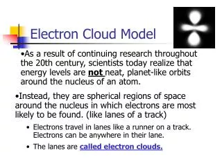
Electron cloud generation, effects Electron cloud sources • Photoemission • Secondary emission, • Electrons accelerated by beam • Beam losses, protons and ions (grazing incidence on walls, collimators) • Ionization of residual gas Secondary processes • Electron-stimulated molecular desorption, vacuum pressure rise/runaway (PEP-II, APS, SPS, RHIC) • Electron cloud trapping in magnetic fields (dipoles, quadrupoles, ion pump fringe field, etc) (HCX, PSR, CESR) • Interference with standard beam diagnostics (SPS) K. Harkay EC at APS Cornell, Feb 2007
Secondary electron emission • Universal curve, peak values surface dependent • max ~1-3 metals, >10 non-metals • Emax 250-400 eV • E1 ~20-50 eV • E2 ~1 keV but much higher at grazing incidence • EC lifetime depends strongly on 0 ~0.5 (CERN, PSR) • Emission has 3 components* • True SE peaks at 1-3 eV, surface independent • Rediffused varies/sensitive to surface • Elastic depends onenergy * M. Furman, M. Pivi, PRSTAB 5, 124404 (2002) Fig. courtesy of R. Kirby K. Harkay EC at APS Cornell, Feb 2007
EC amplification processes Dominant source of EC can vary • Photoemission alone can be sufficient if no antechamber (KEKB, KEK PF, BEPC) • Beam-induced multipacting can lead to large amplification if > 1 (PEP-II, APS) [APS vs BEPC: K. Harkay et al., Proc. 2001 PAC, 671 (2001)] K. Harkay EC at APS Cornell, Feb 2007
Beam-induced multipacting (BIM) Multipacting condition vs. EC distribution, short bunches • Cold-electron model [O. Gröbner, Proc. 10th HEAC, Protvino, 277, 1977] • Multiple kicks, energy distribution (Zimmermann, Ruggiero) • “General” condition: dependence on EC distribution (Furman, Heifets) [K. Harkay, R. Rosenberg, PRST-AB 6, 034402 (2003); L.F. Wang, A. Chao, H. Fukuma, Proc. ECLOUD04 (2004)] LHC, SPS=25ns Fig. courtesy F. Ruggiero and G. Arduini K. Harkay EC at APS Cornell, Feb 2007
Same argument for development of stripes in dipoles: stripe position is where energy gain is near Emax. Stripes move with beam current. K. Harkay EC at APS Cornell, Feb 2007
Impulse kick not valid near beam bunch current 2 mA 10 mA For 40-ps-long (12-mm) positron APS bunches, cloud electrons that are within about 500 μm of the beam center oscillate several times in the bunch potential (calculations are for vertical plane). The transverse rms beam size is 350 μm (horizontal) and 50 μm (vertical). [Courtesy L. Loiacono, from K. Harkay, R. Rosenberg, L. Loiacono, ICFA BD Newsletter 33, Apr 2004] K. Harkay EC at APS Cornell, Feb 2007
1.6 6.4 4.5 mm e- + 45V – Multiplexer Retarding Voltage Picoammeter -300 to +60 V Retarding field analyzer (RFA) RFA measures distribution of EC colliding with walls, trans. eff. 50% Radiation fan at det. #6 for Eg ≥ 4 eV mounting on APS Al chamber behind vacuum penetration (42 x 21 mm half-dim.) mounting on 5-m-long APS chamber, top view, showing radiation fan from downstream bending magnet. Pressure measured locally (3.5 m upstream of EA). K. Harkay EC at APS Cornell, Feb 2007
Advantage of RFA vs. biased electrode RFA, normal (top) vs. angular (bottom) incidence (collector biased +45 V) Biased BPM, electron gun, normal incidence • EC in chamber is not shielded from biased grid or collector • Varying electrode bias voltage • Changes incident electron energy • Changes collection length • Difficult to deduce true wall flux K. Harkay EC at APS Cornell, Feb 2007
Outline • Brief review • Electron cloud generation • Amplification, multipacting • Diagnostics • Experimental observations • Modeling • Summary K. Harkay EC at APS Cornell, Feb 2007
Dependence on bunch spacing Measured (RFA 6) electron wall current (Ic) as a function of bunch spacing, normalized to the total beam current (Ib) (10 bunches; total current shown). The inset shows a conditioning effect of more than a factor of two reduction after 60 Ah of beam operation. K. Harkay EC at APS Cornell, Feb 2007
Energy distribution • Energy distributions from differentiated RFA signals as a function of bunch spacing (units of ) (10 bunches, 2 mA/bunch) • Low-energy part is well fit by a Lorentzian with <E> 2.5 eV and width 4 eV • Long exponential tail on all but 128 • Energy bumps observed for 2 and 4 , but not on longest tail for 7 • Avg energy ~100 eV for e+ beam at 20 ns spacing; ~10 eV for e- beam at 30 ns spacing K. Harkay EC at APS Cornell, Feb 2007
Cloud build-up and saturation EC saturates after 20-30 bunches (middle of straight) Level varies nonlinearly with bunch current (7lrf bunch spacing) • KEKB 6e11 m-3 (no solenoid) (H. Fukuma, ECLOUD02) • APS 10e10 m-3 ( “ ) • PEPII 10e10 m-3 (between solenoids) (A. Kulikov) Calculated EC density at saturation (e+ beam) K. Harkay EC at APS Cornell, Feb 2007
General multipacting condition vs. EC distribution K. Harkay, et al., Proc. 2003 PAC, 3183; ICFA BD Newsletter 33 (2004) RFA vs. POSINST: Peak at 20 ns bunch spac. (7 bkt) sensitive to <δmax>, peak width to rediffused ** Most resonances for 6 – 7 bkt when 1.2 < δmax < 3.8 eV for 1.0 3.0 Cold SE predicts 4 bkt **U. Iriso, also for RHIC (CSEC and ECLOUD), EPAC06 K. Harkay EC at APS Cornell, Feb 2007
SE- vs. PE-dominated No BIM and nearly linear EC density observed in BEPC e+ ring BEPC data courtesy of Z. Guo et al. K. Harkay EC at APS Cornell, Feb 2007
Z-dependence APS: Measured RFAs as function of bunch number, spacing, and distance from photon absorber (2 mA/bunch). KEKB: EC with space charge in solenoid modeled with 3D PIC code Fig. courtesy L. Wang, H. Fukuma, K. Ohmi, E. Perevedentsev, APAC01, 466 (2001) K. Harkay EC at APS Cornell, Feb 2007
APS electron-cloud driven instability, e+ 50 bunches, 90 mA,stripline x Acquired near end (9/28/1998) of positron beam operation: max e- cloud amplification with 7 rf bunch spacing (head of bunch trains at left) 60 bunches, 96 mA, streak camera, x-t K.C. Harkay, R.A. Rosenberg, PRST-AB 6, 034402 (2003) K. Harkay EC at APS Cornell, Feb 2007
Electron beam Right: Measured (RFA 3,6) and simulated (dashed line) wall current vs. bunch spacing. There is additional conditioning of 100 Ah for these data compared to positron data, main plot. Left: Measured wall current as a function of bunch train length, 30 ns spacing. The signal near EA (RFA 1) is always higher than RFA 6. No anomalous pressure rise is observed. Pressure rise was observed for certain fill patterns, but quickly conditioned away K. Harkay EC at APS Cornell, Feb 2007
d Incident electron energy (eV) Modeling with posinst • APS parameters • Posinst input params [Furman, Pivi] • Photon number • Posinst output: • Avg bombardment rate (compare with RFA) • Avg density • Electron nex, ndant, ncoll, nsec • Electron Ekavg, Ekmax (chamber & wall collisions) Measured for APS chambers (courtesy R. Rosenberg), fitted to empirical formula in [Furman, Pivi] [Ref] M. Furman, M. Pivi, PRSTAB 5, 124404 (2002) K. Harkay EC at APS Cornell, Feb 2007
Machine parameters for APS K. Harkay EC at APS Cornell, Feb 2007
APS movie • 10 positron bunches, 2 mA/bunch (4.6e10) • 7-bucket spacing (72.84 = 20 ns) • Multipacting pattern established by 4th bunch • ~12-13 frames per bunch passage • ~1.5 ns/frame • Computation and movie courtesy M. Pivi K. Harkay EC at APS Cornell, Feb 2007
bnch #1 + 1.5 ns (approx) bnch #9 + 4.5 ns + 3 ns + 6 ns + 11.5 ns + 9 ns + 7.5 ns K. Harkay EC at APS Cornell, Feb 2007
2.8ns 20ns 364ns Modeled EC distribution, single turn (10-bunch train) Comparison of max2.2 vs. 3.1; greatest effect at 20 ns spacing 2.8ns 20ns 364ns K. Harkay EC at APS Cornell, Feb 2007
Buildup over bunch train RFA vs. POSINST: Peak at 20 ns bunch spac. (7 bkt) sensitive to <δmax>, peak width to rediffused ** Right: Measured (RFA 1,6) and simulated (dashed line, δmax=3.0) electron wall current as a function of bunch train length, 20 ns bunch spacing, comparing RFAs 65 cm apart. Anomalous pressure rise P is also shown. Left: Comparison with simulated (dashed line, δmax=3.1) electron wall current (Ic) as a function of bunch spacing (10 bunches; 2 mA/bunch). K. Harkay EC at APS Cornell, Feb 2007
Surface conditioning Wall flux at APS reduced 2x after 60 Ah of surface conditioning (inset, left), equivalent to 10-3 C/mm2 dose, consistent with CERN data (Cu). Conditioned Aluminum chamber RFA data consistent with max 2.2. Courtesy N. Hilleret, Two-stream Instab. Workshop, KEK, Japan (2001) K. Harkay EC at APS Cornell, Feb 2007
Modeled effect of space charge, 20 ns bunch spacing K. Harkay EC at APS Cornell, Feb 2007
Summary • Measured electron cloud distribution in APS for bunch trains vs current; positron and electron beam • Strong beam-induced multipacting observed for 20 ns spacing positrons, threshold current; weak (but not zero) effect at 30 ns spacing for electron beams • APS positron operation used much less or much greater than 20 ns spacing: never saw EC effects before dedicated investigation • EC generation depends strongly on maxand rediffused components • Energy distribution different for positrons vs electron beams, confirms expected beam-cloud dynamics • Wall conditioning effect: maxstarted at 3.1, conditioned to 2.2 K. Harkay EC at APS Cornell, Feb 2007
Extra slides K. Harkay EC at APS Cornell, Feb 2007
t = 170 ns Decay time of electron cloud PSR KEKB Courtesy of R. Macek KEKB: 25-30 ns vs. PSR: 170 ns decay time Courtesy of H. Fukuma, Proc. ECLOUD’02, CERN Report No. CERN-2002-001 (2002) K. Harkay EC at APS Cornell, Feb 2007
CERN SPS – LHC-type beams Measured EC distribution in special dipole chamber fitted with strip detectors Qualitatively confirmed simulation showing two stripes Figs courtesy J.M. Jiminez, G. Arduini, et al., Proc. ECLOUD’02, CERN Report No. CERN-2002-001 (2002) K. Harkay EC at APS Cornell, Feb 2007
Proposed electron sweeper for quadrupoles (PSR) Schematic cross section of a proposed electron sweeping detector for a PSR quadrupole. (Courtesy R. Macek, M. Pivi) Snapshot of trapped electrons in a PSR quadrupole 5 ms after passage of the beam pulse. (Courtesy M. Pivi) K. Harkay EC at APS Cornell, Feb 2007
Cloud build-up and saturation APS: EC saturates after 20-30 bunches (middle of straight); level varies nonlinearly with bunch current (7lrf bunch spacing) KEKB: EC saturates after 20-30 bunches per tune shift (4lrf bunch spacing) Figure courtesy of H. Fukuma, Proc. ECLOUD’02, CERN Report No. CERN-2002-001(2002) • Calculated EC density at saturation (e+ beam) • KEKB 6e11 m-3 (no solenoid) • APS 10e10 m-3 ( “ ) • PEPII 10e10 m-3 (between solenoids) (Kulikov’s talk) K. Harkay EC at APS Cornell, Feb 2007
General multipacting condition vs. EC distribution APS: K. Harkay, et al., Proc. 2003 PAC, 3183; ICFA BD Newsletter 33 (2004) L. Wang et al., ECLOUD04: RHIC. KEKB, SNS Most resonances for 6 – 7 bkt when 1.2 < δmax < 3.8 eV for 1.0 3.0 RFA vs. POSINST: Peak at 20 ns bunch spac. (7 bkt) sensitive to <δmax>, peak width to rediffused ** KEKB Modeled EC distrib; RFA agrees APS RFA Cold SE predicts 4 bkt **U. Iriso, also for RHIC (CSEC and ECLOUD), EPAC06 K. Harkay EC at APS Cornell, Feb 2007
Collector Repeller Grid Slots & Screen Pulsed Electrode Trailing edge multipacting at Proton Storage Ring Wideband coherent motion 50-300 MHz (4.4mC/pulse) 7.7mC/pulse LANL Electron Sweeper RFA (~500 V pulse, 80MHz fast electronics added) Prompt electron signal due to trailing-edge multipactor; swept electrons survive gap bunch length = 280 ns Figs. courtesy R. Macek A. Browman, T. Wang K. Harkay EC at APS Cornell, Feb 2007