Download
1 / 27
270 likes | 512 Views
What’s new for 2013 Si8000m / Si9000e / Speedstack / CGen January 2013 by Richard Attrill. New ‘Process Window’ function We have received requests from Si8000m / Si9000e users to provide an option that determines the acceptable parameter range for a given target impedance.

E N D
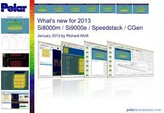
What’s new for 2013 Si8000m / Si9000e / Speedstack / CGen January 2013 by Richard Attrill
New ‘Process Window’ function We have received requests from Si8000m / Si9000e users to provide an option that determines the acceptable parameter range for a given target impedance. For example: If the target impedance is 50 ohms ± 5%, what is the acceptable range of dielectric heights (H1) that can be used? Another example: If the target impedance is 75 ohms ± 5%, what is the acceptable range of trace widths (W1) that can be used? This acceptable range is what some fabricators call the ‘Process Window’ and the following slides show how this new functionality has been implemented.
New ‘Process Window’ function Selecting the new ‘Process Window’ toolbar icon will load the new option
The first stage is to enter the Target Impedance & Tolerance and then select the structure Parameter. On selecting Calculate the minimum, nominal and maximum impedances is displayed. The parameter value for these impedances is then calculated using the Goal Seek technique, with the results displayed in the relevant boxes. In this case, the Process Window for H1 is 3.60 to 5.11
In this example the trace width W1 parameter has been selected. When trace width parameters are chosen both lower and upper widths (W1 / W2) are calculated In this case, the Process Window for W1 is ~5.05 to ~7.26
New coplanar structures Eight new coplanar structures requested by Polarcare customers have been added
New sensitivity analysis crosstalk NEXT / FEXT graph option Trace separation (S1) is selected with a start and end range values from 4 to 50 mils The NEXT / FEXT Display Series is selected and the calculate crosstalk values are plotted against trace separation (S1)
New sensitivity analysis crosstalk NEXT / FEXT graph option Same parameters used on a Edge-Coupled Offset Stripline structure. No far-end crosstalk (FEXT) on stripline structures
New sensitivity analysis crosstalk NEXT / FEXT graph option Extra crosstalk NEXT / FEXT columns now exist in Results tab. FEXT calculation requires length of line (LL) and rise time (Tr)
New sensitivity analysis crosstalk NEXT / FEXT graph option This feature is available with the Si9000e Recommended reading: Signal Integrity Simplified by Eric Bogatin, Chapter 10 – Cross Talk in Transmission Lines
Improved calculation of low frequency resistance Si9000e 2013 has an updated Calc Engine that improves low frequency resistance calculations
Other enhancements Updated .Si8 and .Si9 file formats to support new coplanar structures, Extended Substrate Data and Surface Roughness checkbox status flags – Si8000m and Si9000e Frequency dependent calculation enhancements including increased result precision for data grids and clipboard formats – Si9000e
New ‘Processed Thickness’ displayable column Processed Thickness, a single column that contains the conductor Finished Thickness and dielectric Isolation Distance. Totalling these fields equals the actual Stack Up Thickness
New ‘Processed Thickness’ displayable column Processed Thickness, shown on the Technical Report
Design rule check (DRC) improvements New drill aspect ratio checks
Other Speedstack enhancements Technical report improvements Impedance structure highlighting improvements form now Advanced structures
New SET2DIL Revision 3 Coupon Style (beta) New launch pattern with additional ground via Fibre weave mitigation
New SET2DIL Revision 3 Coupon Style (beta) New coupon properties tab to accommodate the new options
Target Release Schedule Si8000m / Si9000e / Speedstack 2013 : Q1 CGen 2013 : Q1 Windows 8 2013 software releases are compatible with Windows 8
For more information: Contact Polar now: Phone USA / Canada / MexicoKen Taylor ( 503) 356 5270 Asia / Pacific Terence Chew +65 6873 7470 Japan Kentaro Takano +81 45 339 0155 UK / EuropeNeil Chamberlain +44 23 9226 9113 Germany / Austria / Switzerland Hermann Reischer +43 7666 20041-0 www.polarinstruments.com