Download
1 / 22
220 likes | 386 Views
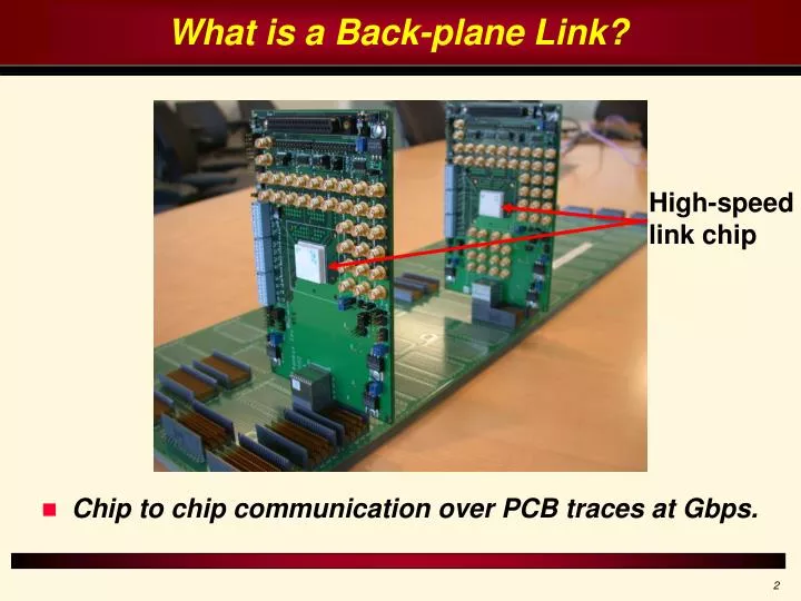
What is a Back-plane Link?. Chip to chip communication over PCB traces at Gbps. High-speed link chip. Channel Characteristics. Frequency domain: Smooth fall-off due to loss. Usually a few deep notches due to impedance mismatches. Time Domain: A few large pre and post cursor ISI taps.

E N D
What is a Back-plane Link? • Chip to chip communication over PCB traces at Gbps. High-speed link chip
Channel Characteristics • Frequency domain: • Smooth fall-off due to loss. • Usually a few deep notches due to impedance mismatches. • Time Domain: • A few large pre and post cursor ISI taps. • A long reflection tail.
As signaling rates increase, links channels look more and more like DSL channels. Can We Do Multi-tone?
Discrete Multi-tone • Discrete time processing at the Rx requires sampling at the Nyquist rate. • 20GSamples/Sec for 10GHz channel use! • Need sufficient sampling resolution at the Rx to have non-dominant quantization noise. • 10-12 bits. • The fastest reported ADC operates @ 20GSamp/Sec but also consumes 9W and only has 5 effective bits! • ADC requirements are prohibitive.
System Characteristics • Signaling rate close to fundamental limits of IC technology. • Discrete time processing at the Rx generally very hard. • Processing at the Tx very limited by complexity. • Several noise sources other than Thermal. • Sampling Jitter • Carrier phase noise • …
State of the Art Links Technology • Baseband processing only • 2PAM and 4PAM • Tx linear precoding (pre-equalization) • Rx DFE • Can achieve 10Gbps on channels without a notch. • Performance limited by channel ISI • Equivalently: precoding loss. • Have to do MT! How Do We Do Multi-tine?
Outline • AMT Architecture • Analysis Framework • System Level Tradeoffs • Comparison with BB
Analog MT • Create data sub-channels using analog filters and mixers. • Some signal processing at the Tx or Rx to compensate for ISI, RF imperfections, …
AMT Advantages • Less precoder loss by operating over narrower sub-channels. • Link channels are relatively smooth • Not too many sub-channels required • Parallelization • Sub-channels operate at a fraction of overall signaling rate. • Can design better circuits at lower rates • Less sampling jitter, slicer offset, … • Compatibility with BB • All BB techniques can be readily applied to the sub-channels. • Appealing for the industry.
AMT Issues • Inter-channel Interference (ICI). • Analog on-chip filters not too sharp, not too accurate • Need a lot of Guard-band or high order filters to avoid ICI • Have to compensate for ICI by signal processing • RF overhead • Have to find out how much it is. • What the requirements are on the RF circuits.
Transmit Matrix Precoding • Relax analog filtering requirements by matrix precoding. • Cross precoding only required to immediate neighbors. • Summation nodes are implemented by transistors. • Have to remain in linear region. Headroom Constraint
System Formulation • Can model the system as MIMO: Y = X YW + N • For the kth sub-channel: BER Constraint: Peak Voltage Constraint:
Optimization Framework • Constraints convex in precoder taps ( W ) • Also functions of bit loading ( ) • For fixed bit-loading, can verify feasibility, find WOPT • Should do combinatorial search to find bOPT. • Can find tight upper bounds for ( ) though – Just ignore ICI.
System Tradeoffs • Many opportunities for good engineering through trading complexities. • Precoder complexity – Guard BW • Precoder complexity – LPF BW • … • Hard to find the optimum setting.
Comparison with BB • Find maximum achievable rate by BB and MT over a smooth (NELCO) and a dispersive (FR4) channel. • Compare performance and complexity. • Should assume some specs for noise figure, jitter, … • Easy for BB – just look at available systems • Hard for MT – try to be conservative • Look at performance when one noise level changes slightly
Comparison Assumptions • MT: • 1GHz sub-channel BW • 25% guard band • 4th order Butterworth LPF • Same noise figure for BB and MT • Same clock characteristics for BB (sampling) and MT sub-channels (carriers) • Pessimistic for MT. • In practice can derive all clocks form the highest frequency clock. • Assume zero slicer offset for both MT and BB • Find minimum required gain before the decision device for this assumption to hold.
Overall Data Rate • More than 75% increase compared to BB over the smooth channel (NELCO) • More than 100% increase compared to BB over the dispersive channel (FR4)
Bit Loading NELCO FR4 • MT wins gradually over the smooth channel (NELCO) • MT wins by passing the notch over the dispersive channel (FR4)
NELCO FR4 Gain Requirements • Assume that a typical slicer has 10mV of offset. • Find the required amount of gain before the slicer in each sub-channel so that the initial 0mV offset assumption holds. • Most sub-channels require a gain of less than 10 (20dB). • BB requires: • NELCO: 31dB @ 3.6GHz BW. • FR4: 12dB @ 1.8GHz BW.
Precoding Requirements NELCO FR4 • AMT overall: • NELCO: 200 @ 1GHz • FR4: 100 @ 1GHz • BB overall: • NELCO: 77 @ 7.2GHz ~ 550 @ 1GHz • FR4: 32 @ 3.6GHz ~ 115 @ 1GHz • AMT has some advantage.
Sensitivity to Noise Only FR4 shown Phase noise power proportional to signal power • Keep all noise sources; perturb one by ±6dB. • In all cases, change in performance is ±10% of nominal. • Phase noise dominant in low-loss region. • Thermal dominant in high-loss region.
Final Notes • About 2x improvement with conservative assumptions. • RF requirements for AMT are not prohibitive. • 4th order LPF • DLL jitter specs • Gain of ~10 per sub-channel • Less signal processing power compared to BB • Goal was to show the fundamental advantage. • Simplest form of signal processing was used. • Many opportunities for performance improvement by better Tx/Rx signal processing.