Thrust Allocation
This study presents a comprehensive approach to optimal thrust allocation in autonomous vessels, focusing on the minimization of thrust errors and fuel consumption. By establishing a dynamic model of thrusts and azimuth angles, the research overcomes challenges such as singular configurations and forbidden zones. Advanced techniques like Kalman filtering, adaptive control, and effective noise reduction strategies are utilized to achieve precise positioning and reduced wear on propulsion systems. The outcome is a robust framework that ensures smooth maneuverability while addressing the complexities of azimuth thruster control.

Thrust Allocation
E N D
Presentation Transcript
Thrust Allocation Ole Jakob Sørdalen, PhD Counsellor Science & Technology The Royal Norwegian Embassy, Singapore
Controller architecture • Sensor signal processing • Signal QA • Filtering and weighting • Vessel Model • Separate LF/WF model • Kalman filter estimator • Mooring model • Optimal Control • Positioning and damping • Reduce fuel, tear and wear • Mooring line break compensation • Feedforward control • Wind load compensation • Reference model tracking • Optimal thrust allocation • Adaptive control
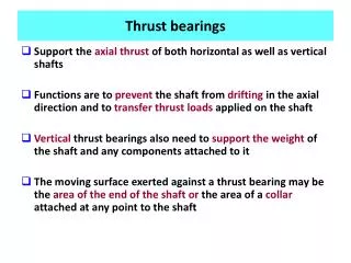
Problem statement Given desired forces and moment from the controller, tc =[txc, tyc, tyc]T. Determine thrusts T=[T1, T2,..., Tn]T and azimuth angles a=[a1, a2,..., an]T so that • ||A(a) T - tc|| is minimal to minimize the error • ||T|| is minimal to minimize fuel consumption • ai(t) is slowly varying to reduce wear and tear Assumption here: Thrusters are bi-directional
Challenges • Singularities: the singular values of A(a) can be small; A(a) T = t , simple pseudo inversion can give high gains and high thrust • An azimuth thruster cannot be considered as two independent perpendicular thrusters since the rotation velocity is limited • If the thruster is not symmetric, how should the azimuth respond to 180o changes of desired thrust directions? • Forbidden zones
T 3 t t T y x 1 T t 2 y Singularities There is an azimuth angle where det A(ais) = 0 A(ais) cannot be inverted Example of a singular configuration:
Singular Value Decomposition Any m x n matrix A can be factored into A = U S VT Where U snd V are orthogonal matrices. S is given by
About SVD ... • Coloumns of U: orthonormal eigen vectors of AAT • Coloumns of V: orthonormal eigen vectors of ATA • si = sqrt (eig(ATA) i) • Pseudo inverse of A: A+ = V S+ UT • The least square solution to Ax = y is x = A+y i.e. either min ||Ax – y||2 or min ||x|| 2 Can use weighted LS.
Example: plot of smallest singular value Bow azimuth fixed 90o. Aft azimuts rotate
Fixed angle between aft azimuths s < 0.05
How to determine angles a? • Consider azimuth thrusters as two perpendicar fixed thrusters • New (expanded) relation: AeTe = t • desired ”expanded” thrust vector Ted: Ted = A+etc
How to determine thrust T? • Note: T = A+(af)tc large T close to singular configurations! • Modified pseudo inverse: Ad+ = V Sd+ UT T = V Sd+ UTtc
Geomtrical interpretation • Commanded thrust in directions representing small singular values are neglected • This is GOOD • Azimuth angles are always oriented towards the mean environment forces & torques • Other commanded forces typically due to noise efficient ”geometrical” filtering of this noise
Features • Automatic azimuth control • Automatic avoidance of forbidden sectors: not shown here • Optimal direction control • Smooth turning • Optimal singularity handling • Avoidance of unnecessary use of thrust • Reduced wear and tear of propulsion devices • Optimal priority handling • Among thruster devices • Among surge, sway, yaw