Download
1 / 26
270 likes | 291 Views
Dive into the significance of Q2=L/R2C in electrical components, resonance curves, and phasor diagrams in power physics. Learn how to connect and visualize complex concepts with real-world examples. Explore the relationships between inductors, capacitors, and resistors in RLC circuits through equations and phasor diagrams. Discover the key to mastering power physics and solving typical problems efficiently. Master the principles of peak voltage, impedance, resonance, and energy storage in electrical circuits. Enhance your understanding of transformers and how they relate to overall circuit behavior.

E N D
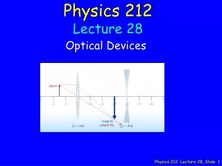
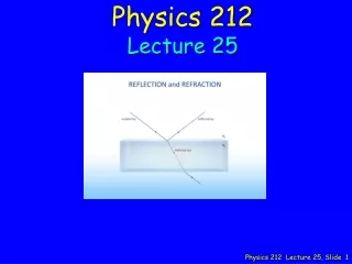
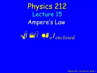
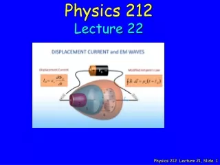
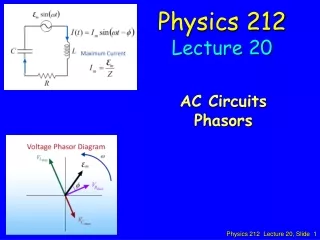
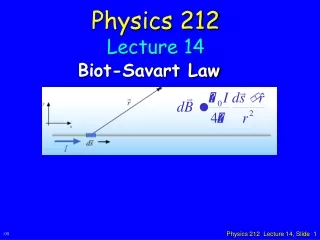
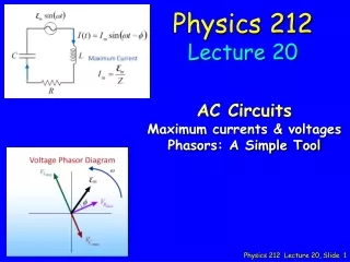
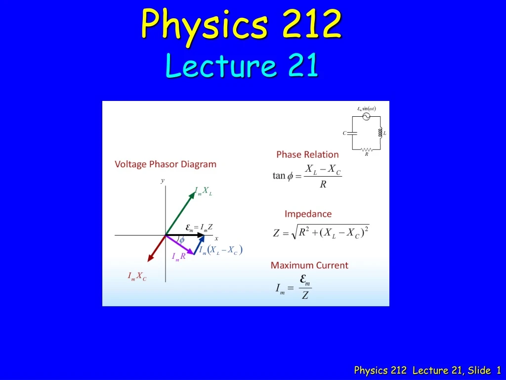
Physics 212 Lecture 21
Music • Who is the Artist? • Earth, Wind & Fire • War • Tower of Power • Average White Band • Chicago Why? Topic for today = Power Physics 212 Lecture 21
“Oh my god that was horrible please don’t make me memorize all that.” “none of this makes sense please be thurough in lecture” We’ll do our best to restate the Big Ideas and give examples “What significance does Q2=L/R2C have in electrical components?” Shape of resonance curve (I vs. w) “This doesn’t seem conceptually hard but there are tons of new equations and relations between variables.” It’s all still based on the phasor diagram! “i dont see how the transformer relates..” Short review + demo Your Comments “Could you better explain the last lecture and how it leads into this? It looks like its just something you have to stare at for a while but once it clicks then its really easy. I’m having trouble with visualizing the phase diagram and this whole pre lecture was gibberish to me. Not one thing sunk in.” ABSOLUTELY We will connect the two today.. 05
What Did We Learn in Office Hours This Week? Imax XC C Imax XL emax L R Imax R emax = Imax Z V = Projection along Vertical Imax XL Imax(XL-XC) w Imax R XL = wL XC = 1/wC Imax R XL-XC f Imax XC R PHASORS ARE THE KEY !! FORMULAS ARE NOT ! START WITH PHASOR DIAGRAM DEVELOP FORMULAS FROM THE DIAGRAM !!
General RLC Example 07 C L R XL R XC • “Ohms” Law for each element • NOTE: Good for PEAK values only) • Vgen = Imax Z • VResistor = Imax R • Vinductor = Imax XL • VCapacitor = Imax XC • Typical Problem A generator with peak voltage 15 volts and angular frequency 25 rad/sec is connected in series with an 8 Henry inductor, a 0.4 mF capacitor and a 50 ohm resistor. What is the peak current through the circuit?
General RLC Example 12 C L R XL R XC • “Ohms” Law for each element • Vgen = I Z • VResistor = I R • Vinductor = I XL • VCapacitor = I XC • Typical Problem A generator with peak voltage 15 volts and angular frequency 25 rad/sec is connected in series with an 8 Henry inductor, a 0.004 Farad capacitor and a 50 ohm resistor. What is the peak current through the circuit? Which element has the largest peak voltage across it? A) Generator E) All the same. B) Inductor C) Resistor D) Capacitor
General RLC Example 14 C L R XL XL Z25 Z20 R R XC XC • “Ohms” Law for each element • Vgen = I Z • VResistor = I R • Vinductor = I XL • VCapacitor = I XC • Typical Problem A generator with peak voltage 15 volts and angular frequency 25 rad/sec is connected in series with an 8 Henry inductor, a 0.4 mF capacitor and a 50 ohm resistor. What is the peak current through the circuit? What happens to the impedance if we decrease the angular frequency to 20 rad/sec? A) Z increases B) Z remains the same C) Z decreases (XL-XC): (200-100) (160-125)
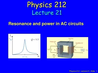
Resonance XL increases with w Z = R at resonance XC increases with 1/w Z R XC XL is minimum at resonance w0 Resonance: XL = XC Frequency at which voltage across inductor and capacitor cancel R is independent ofw 10
In general Umax = max energy stored DU = energy dissipated in one cycle at resonance Off Resonance Z
Checkpoint 1a Consider two RLC circuits with identical generators and resistors. Both circuits are driven at the resonant frequency. Circuit II has twice the inductance and 1/2 the capacitance of circuit I as shown above. Compare the peak voltage across the resistor in the two circuits A. VI > VII B. VI = VIIC. VI < VII “Circuit II has twice the impedance and therefore half the peak current and resistor voltage.” “They would be the same because the circuit has the same impedance.” “V must be less across the resistor to account for increased voltage in the capacitor and inductor”
Imax XL Imax XL Imax R Imax R Imax XC Case 1 Case 2 Imax XC Checkpoint 1a Consider two RLC circuits with identical generators and resistors. Both circuits are driven at the resonant frequency. Circuit II has twice the inductance and 1/2 the capacitance of circuit I as shown above. Compare the peak voltage across the resistor in the two circuits A. VI > VII B. VI = VIIC. VI < VII Resonance: XL = XC Z = R Same since R doesn't change
Checkpoint 1b Consider two RLC circuits with identical generators and resistors. Both circuits are driven at the resonant frequency. Circuit II has twice the inductance and 1/2 the capacitance of circuit I as shown above. Compare the peak voltage across the inductor in the two circuits A. VI > VII B. VI = VIIC. VI < VII “The peak voltage across the inductor is Imax/(wL) which is half as big in the second case.” “V is dependent on change in current, which is dependent on E, which has the same formula in both cases” “voltage is I times wL i think and inductor 2 has twice the inductance while the w is the same in both cases”
Imax XL Imax XL Imax R Imax R Imax XC Case 1 Case 2 Imax XC Checkpoint 1b Consider two RLC circuits with identical generators and resistors. Both circuits are driven at the resonant frequency. Circuit II has twice the inductance and 1/2 the capacitance of circuit I as shown above. Compare the peak voltage across the inductor in the two circuits A. VI > VII B. VI = VIIC. VI < VII Voltage in second circuit will be twice that of the first because of the 2L compared to L
Checkpoint 1c Consider two RLC circuits with identical generators and resistors. Both circuits are driven at the resonant frequency. Circuit II has twice the inductance and 1/2 the capacitance of circuit I as shown above. Compare the peak voltage across the capacitor in the two circuits A. VI > VII B. VI = VIIC. VI < VII “The current will decrease by a factor greater than 2 which decreases peak voltage.” “they must equal each other because the circuit is resonant” “Xc would be twice as higher as C is halved in the second case. As such, the peak voltage across the capacitor would be higher in the second case.”
Imax XL Imax XL Imax R Imax R Imax XC Case 1 Case 2 Imax XC Checkpoint 1c Consider two RLC circuits with identical generators and resistors. Both circuits are driven at the resonant frequency. Circuit II has twice the inductance and 1/2 the capacitance of circuit I as shown above. Compare the peak voltage across the capacitor in the two circuits A. VI > VII B. VI = VIIC. VI < VII The peak voltage will be greater in circuit 2 because the value of XC doubles.
Checkpoint 1d Consider two RLC circuits with identical generators and resistors. Both circuits are driven at the resonant frequency. Circuit II has twice the inductance and 1/2 the capacitance of circuit I as shown above. At the resonant frequency, which of the following is true? A. Current leads voltage across the generator B. Current lags voltage across the generator C. Current is in phase with voltage across the generator “the inductor has more voltage than the capacitor” “The current is in phase with the resistor which means it lags the voltage of the generator.” “At the resonant frequency, XL=XC, so the circuit behaves as if the resistor is the only element present.”
Imax XL Imax XL Imax R Imax R Imax XC Case 1 Case 2 Imax XC Checkpoint 1d Consider two RLC circuits with identical generators and resistors. Both circuits are driven at the resonant frequency. Circuit II has twice the inductance and 1/2 the capacitance of circuit I as shown above. At the resonant frequency, which of the following is true? A. Current leads voltage across the generator B. Current lags voltage across the generator C. Current is in phase with voltage across the generator The voltage across the inductor and the capacitor are equal when at resonant frequency, so there is no lag or lead.
Power C L R < I2 R > = Irms2 R • P = IV instantaneous always true • Difficult for Generator, Inductor and Capacitor because of phase • Resistor I,V are ALWAYS in phase! P = IV = I2 R • Average Power • Inductor and Capacitor = 0 ( < sinwtcoswt > = 0 ) • Resistor • <I2R> = <I2 >R = ½ I2peak R RMS = Root Mean Square Ipeak = Irms sqrt(2)
Power Line Calculation • If you want to deliver 1500 Watts at 100 Volts over transmission lines w/ resistance of 5 Ohms. How much power is lost in the lines? • Current Delivered: I = P/V = 15 Amps • Loss = IV (on line) = I2 R = 15*15 * 5 = 1,125 Watts! • If you deliver 1500 Watts at 10,000 Volts over the same transmission lines. How much power is lost? • Current Delivered: I = P/V = .15 Amps • Loss = IV (on line) = I2R = 0.125 Watts DEMO
Transformers(Robots in Disguise, as many of you said) • Application of Faraday’s Law • Changing EMF in Primary creates changing flux • Changing flux, creates EMF in secondary • Efficient method to change voltage for AC. • Power Transmission Loss = I2R • Power electronics
Follow Up from Last Lecture C V ~ L R (A) (B) (C) (D) X X X VR VR VL VL V V V V VL < VC if current leads generator voltage VC VC VL VL VR VR VC VC Consider the harmonically driven series LCR circuit shown. Vmax = 100 V Imax = 2 mA VCmax = 113 V (= 80 sqrt(2)) The current leads generator voltage by 45o (cos=sin=1/sqrt(2)) L and R are unknown. What does the phasor diagram look like at t = 0? (assume V = Vmaxsinwt) V = Vmax sinwt V is horizontal at t = 0 (V = 0)
Follow Up: Resonance C V ~ L R At resonance (w0) Original w VL f VR VR XL increases XC decreases VL V w increases V VC VC Consider the harmonically driven series LCR circuit shown. Vmax = 100 V Imax = 2 mA VCmax = 113 V (= 80 sqrt(2)) The current leads generator voltage by 45o (cos=sin=1/sqrt(2)) L and R are unknown. How should we change w to bring circuit to resonance? (A) decrease w (B) increase w (C) Not enough info At resonance XL = XC
Follow Up: Resonance C V ~ L R If w is increased by a factor of f: XL increases by factor of f XC decreases by factor of f Consider the harmonically driven series LCR circuit shown. Vmax = 100 V Imax = 2 mA VCmax = 113 V (= 80 sqrt(2)) The current leads generator voltage by 45o (cos=sin=1/sqrt(2)) L and R are unknown. By what factor should we increase w to bring circuit to resonance? i.e. if w0 = fw, what is f? (A) (B) (C) (D) At resonance XL = XC f
Follow Up: Resonance C V ~ L R (A) (B) (C) Consider the harmonically driven series LCR circuit shown. Vmax = 100 V Imax = 2 mA VCmax = 113 V (= 80 sqrt(2)) The current leads generator voltage by 45o (cos=sin=1/sqrt(2)) L and R are unknown. What is the maximum current at resonance ( Imax(w0) ) At resonance XL = XC