Safety Critical Systems
Safety Critical Systems . T 79.5303 Safeware - Design for safety hardware and software Ilkka Herttua. Requirements Model. Requirements Analysis. Test Scenarios. Test Scenarios. System Acceptance. Requirements Document. Functional / Architechural - Model. System

Safety Critical Systems
E N D
Presentation Transcript
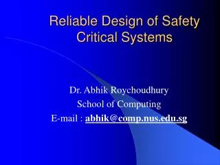
Safety Critical Systems T 79.5303 Safeware - Design for safety hardware and software Ilkka Herttua
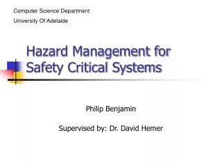
Requirements Model Requirements Analysis Test Scenarios Test Scenarios System Acceptance Requirements Document Functional / Architechural - Model System Integration & Test Systems Analysis & Design Specification Document Knowledge Base * Software Design Module Integration & Test Software Implementation & Unit Test * Configuration controlled Knowledge that is increasing in Understanding until Completion of the System: • Requirements Documentation • Requirements Traceability • Model Data/Parameters • Test Definition/Vectors V - Lifecycle model
Designing for Safety (Analyse) • Faults groups - requirement/specification errors - random component failures - systematic faults in design (software - process) • Approaches to tackle problems - right system architecture (fault-tolerant) - reliability engineering (component, system) - quality management (designing and producing processes)
Designing for Safety (Architecture) • Hierarchical design - simple modules, encapsulated functionality - separated safety kernel – safety critical functions • Maintainability - preventative versa corrective maintenance - scheduled maintenance routines for whole lifecycle - easy to find faults and repair – short MTTR (mean time to repair) • Reduce human error - Proper HMI
HardwareComponent reliability prediction Electronic Components Based on probability calculation and statistical data MIL-Handbook 217 – experimental data on actual device behaviour Manufacture information and allocated circuit types Bath tube curve; burn in – useful life – wear out
Hardware Faults Intermittent faults Fault occurs and recurs over time (loose connector) Transient faults Fault occurs and may not recur (lightning) Electromagnetic interference Permanent faults Fault persists / physical processor failure (design fault – over current or temperature)
Safety Critical System Fault Detection: Routines to check that hardware works Signal comparisons Information redundancy –parity check etc.. Watchdog timers Bus monitoring – check that processor alive Power monitoring
Hardware Design Guideline • Fault tolerance hardware- Achieved mainly by redundancy- Adds cost, weight, power consumption, complexityOther means:- Improved maintenance, single system with better materials (higher mean time between failure - MTBF)
Redundancy Methods Active Redundancy: Redundant units are always operating in parallel Dynamic Redundancy (standby): Failure has to be detected Changeover to other module
Hardware redundancy techniques Active techniques: Parallel (k of N) Voting (majority/simple) Standby techniques : Operating - hot stand by Non-operating – cold stand by
(7) (8) (6) (1) (2) (3) (4) (5) Redundancy Techniques Active Standby Parallel Voting Non-Operating Operating Majority Vote Gate Connector Simple Duplex Bimodal Simple Adaptive Redundancy Techniques
Simple Parallel RedundancyActive - Type 1 In its simplest form, redundancy consists of a simple parallel combination of elements. If any element fails open, identical paths exist through parallel redundant elements.
A1 S1 OR AND DL ED AND A2 S2 OR Duplex Parallel RedundancyActive - Type 2 This technique is applied to redundant logic sections, such as A1 and A2 operating in parallel. It is primarily used in computer applications where A1 and A2 can be used in duplex or active redundant modes or as a separate element. An error detector at the output of each logic section detects noncoincident outputs and starts a diagnostic routine to determine and disable the faulty element.
A1 A2 MVT A3 An Simple Majority VotingActive - Type 4 Decision can be built into the basic parallel redundant model by inputting signals from parallel elements into a voter to compare each signal with remaining signals. Valid decisions are made only if the number of useful elements exceeds the failed elements.
A1 Power Output A2 A1 Power Output A2 Non-Operating RedundancyStandby - Type 7 A particular redundant element of a parallel configuration can be switched into an active circuit by connecting outputs of each element to switch poles. Two switching configurations are possible. 1) The element may be isolated by the switch until switching is completed and power applied to the element in the switching operation. 2) All redundant elements are continuously connected to the circuit and a single redundant element activated by switching power to it.
Safety Critical Hardware Avoid commercial microprocessors - No safety firmware, least assurance Redundancy makes better, but common failures possible Fabrication failures, microcode and documentation errors Use components which have history and statistics.
Safety Critical Hardware 2. Use special reliable microprocessors Collins Avionics/Rockwell AAMP2 Used in Boeing 747-400 (30+ pieces) High cost – bench testing, documentation, formal verified functionality Other models: SparcV7, TSC695E, ERC32 (ESA radiation-tolerant), 68HC908GP32 (airbag)
Safety Critical Hardware 3. Programmable Logic Controllers (PLC) Contains power supply, interface and one or more processors, used in industrial application - chemical processes, infrastructure control – water, heat, electricity Designed for high mean time between failure (MTBF) Solid Firmware and application software stored in non volatile memory Programmed with simple ladder or function block diagrams
SoftwareProcess guideline Software development: Normally iteration is needed to develop a working solution. (writing code, testing and modification). In non-critical environment code is accepted, when tests are passed. Testing is not enough for safety critical application – Software needs an assessment process: dynamic/static testing, simulation, code analysis and formal verification.
Safety Critical Software Dependable and High Quality Detailed Process plan for the whole development and testing phases Work discipline – recorded supervision Well documented – easier to validate Quality management Validated/verified
Safety-Critical Software Faults - In Requirements: requirements are not specifying the environment in which the software will be used or unambiguous requirements In Design: not satisfying the requirements or documentation insufficient In Code: generated code is not conforming with the design.
Safety-Critical Software Common faults: Subprogram effects: Definition of a called variable has been changed. Definitions aliasing: Names referred to the same storage location. Initialising failures: Variables have been used as assigned values. Memory management: Buffer, stack and memory overflows Expression evaluation errors: Divide-by-zero/arithmetic overflow
Software Programming Language selection: Logical soundness: Unambiguous definition of the language- no dialects of C++ Simple definitions: Complexity can lead to errors in compliers or other support tools Expressive power: Language shall support to express domain features efficiently and easily Security of definitions: Violations of the language definition shall be detected Verification: Language supports verification, proving that the produced code is consistent with the specification. Memory/time constrains: Stack, register and memory usage are controlled.
Safety Critical Software Language comparison: Structured assembler (wild jumps, exhaustion of memory, well understood) Ada (wild jumps, data typing, exception handling, separate compilation) Subset languages: CORAL, SPADE and Ada (Alsys CSMART Ada kernel, AdaCore&Spark) Validated compiler for Ada Available expertise: with common languages higher productivity and fewer mistakes, but C not approved in all applications.
Software Languages used : Avionics uses mostly Ada, but for Boeing 747-400 about 75 languages were used. ESA mandated Ada for mission critical systems. NASA Space station in Ada, some systems with C and Assembler. Car ABS systems with Assembler. Train control systems with Ada.. Medical systems with Ada and Assembler Nuclear Reactors core and shut down system with Assembler, migrating to Ada.
Safety Critical Software Tools High reliability and validated tools are required: Faults in the tool can result in faults in the safety critical software. Widespread tools are better tested Use confirmed process of the usage of the tool Analyse output of the tool: static analysis of the object code Use alternative products and compare results Use different tools (diversity) to reduce the likelihood of wrong test results.
Safety Critical Software Design guidelines 1 New software features add complexity, try to keep software simple Plan for avoiding human error – unambiguous human-computer interface Removal of hazardous module (Ariane 5 unused code)
Safety Critical Software Designing guidelines 2 Add barriers: hard/software locks for critical parts Minimise single point failures: increase safety margins, exploit redundancy and allow recovery. Isolate failures: don‘t let things get worse. Fail-safe: panic shut-downs, watchdog code Avoid common mode failures: Use diversity – different programmers, n-version programming
Safety Critical Software Designing guidelines 3 Fault tolerance: Recovery blocks – if one module fails, execute alternative module. Don‘t relay on complex operating system in most critical application.
Safety Critical Software Software tool faults: - Faults in software tools (development/modelling) can results in system faults. Techniques for software development (language/design notation) can have a great impact on the performance or the people involved and also determine the likelihood of faults. The characteristics of the programming systems and their runtime determine how great the impact of possible faults on the overall software subsystem can be.
Practical Design Process (By I-Logix tool manufacture – Statemate)
Safety Critical Software Higher integrity software: Simplify: Code contains only minimum features and no unnecessary or undocumented features or unused executable code Diversity: Data and control redundancy Multi-version programming: shared specification leads to common-mode failures, but synchronisation code increases complexity
Home assignments 2 a • Neil Storey’s book: Safety Critical Computer Systems - 5.10 Describe a common cause of incompleteness within specifications. How can this situation cause problems? • 9.17 Describe the advantages and disadvantages of the reuse of software within safety critical projects. Cont.
Home assignments 2 b • 7.15 A system may be described by the following reliability model, where the numbers within the boxes represent the module reliability. Calculate the system reliability. Email by 27. March to herttua@uic.asso.fr 0,7 0,7 0,9 0,7 0,98 0,97 0,99