EXPERIMENTS IN OPTICS
580 likes | 977 Views
EXPERIMENTS IN OPTICS. R.V.MEHTA Lecture delivered at Science Academies'’ 57 th Refresher Course in Physics, P.D.Patel Institute ,CHARUSAT, Changa, 28 March,2014. Importance of Experiments.

EXPERIMENTS IN OPTICS
E N D
Presentation Transcript
EXPERIMENTS IN OPTICS R.V.MEHTA Lecture delivered at Science Academies'’ 57th Refresher Course in Physics, P.D.Patel Institute ,CHARUSAT, Changa, 28 March,2014
Importance of Experiments • What is an Experiment (a scientific procedure undertaken to make a discovery, test a hypothesis, or demonstrate a known fact. Example Michelson Morley experiment to test hypothesis of ether, Davison –Germar exp. To test hypothesis of matterwaves. • Practical( one can learn a scientific topic very easily by performing a practical and writing a report in true spirit of scientist. This learning is useful in many walks of life like better understanding of concepts, future carrier for research, development of analytical treatment of any event. Useful for any carrier or even in life too.) • Difference between Experiments and practical( Practical is a class room experiment. Useful for learning a method to demonstrate a well established theory. Fresnel prism exp., and Newton’s rings exp., to verify Huygens wave theory of light etc. • Experiment and research( Experimental research is used for purpose of testing a theory or a hypothesis)
Ancient Time • Philosophy and Science • Foundation of Natural sciences (1) Aristotle (2)Galileo (3) Newton
Aristotle • According to Aristotle philosophy of reasoning is "science". Note, however, that his use of the term science carries a different meaning than that covered by the term "scientific method". For Aristotle, "all science is either practical, poetical or theoretical" . By practical science, he means ethics and politics; by poetical science, he means the study of poetry and the other fine arts; by theoretical science, he means physics, mathematics and metaphysics.
Importance of observations • Galileo proposed that a falling body would fall with a uniform acceleration, as long as the resistance of the medium through which it was falling remained negligible, or in the limiting case of its falling through a vacuum. He also derived the correct kinematical law for the distance travelled during a uniform acceleration starting from rest—namely, that it is proportional to the square of the elapsed time ( d ∝ t 2 ).
Scientific Method • Galileo showed a remarkably modern appreciation for the proper relationship between mathematics, theoretical physics, and experimental physics. • He improved telescope. Designed compound microscope and performed experiments with these.
Newton’s contribution in Optics • Newton has contributed significantly in several • Fields of physics like mechanics, fluid mechanics • etc. we discuss his contributions in OPTICS. • 1. Specturm ofwhite light • 2. Interference – Newton’s rings • (He was not in favor of wave theory) • I have deliberately shown longer height of Newton to impressed his influence on Science community. Hygens was afraid of Publishing wave theory of light. It was Fresnel who mathematically showed that only wave theory can explain Young’s double slit experiment. This was beginning of Modern Optics.
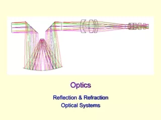
FUNDAMENTAL EXPERIMENTS OF MODERN OPTICS • 1. WAVE NATURE OF LIGHT. • 2. ETHER AND SPEED OF LIGHT. • 3. GRAVITY BENDS THE LIGHT. • 4. LASER. • 5. NONLINEAR OPTICS
We shall not discussed here further history of experiments in physics –particularly in optics but limits ourselves to “ textbook optics”. Here , role of experiments are to verify predictions based on theory.
Laboratory Course • The primary goal of LABORATORY course is to lead the undergraduate students to the discovery, through experimental investigation, of the dual character of light (photons and waves), and to understand the link between the two characteristics of light through spectroscopic measurements. Experiments of spectroscopy show in a very clear way that a photon is actually a wave train and brings the modern physics into a modern optics lab. • Another goal is to teach certain experimental techniques of optics, like interferometry and spectroscopy, which are widely used in industry and research, today.
Laser Pointers • Laser pointers also know as laser penlights, have become very affordable recently due to new developments in laser technology. They are used in aligning of other lasers, laying pipes in construction, and as aiming devices for firearms. • Laser pointer can be use to observe the interference, diffraction and polarization of light in college physics laboratory. Laser pointers can be used to produce holograms. • We shall show that such pointer is also useful to study FT and PBG.
Contd. • We shall discuss here the following : • Basic Experiments • Fourier Transform • Photonics
Experiments with laser pointerBasic Experiments1.Interference
λ =( d/m) ( ym / [L2 + ym2]1/2 ) one has tomeasureym along the meter stick from the central bright line to the mth line. d is grating element and L is the distance between stick and grating. Similar experiment can be carried out for a thin wire. Here,
Diffraction at Wire aλ = dsinθ θm ~ ( dm/2L ) • mλ = asinθm • θm ~ ( dm/2L ) a is width of the slit, dm is dist.bet. Central bright spot to the mth fringe, L is the dist. bet. screen and slit.
Polarization Experiments • Set Up for Mallu’s Law
Fourier Optics • In physics and engineering Fourier series is widely used. It decomposes periodic functions or periodic signals into the sum of a (possibly infinite) set of simple oscillating functions, namely sines and cosines or complex exponentials. • Similarly The Fourier transform is a mathematical transformation employed to transform signals(periodic as well as non-periodic) between time domain and frequency domain. FT has many applications in physics and engineering.
If s(x) denotes a function of the real variable x, and s is integrable on an interval [x0, x0 + P], for real numbers x0 and P. It is possible to represent s in that interval as an infinite sum, or series, of harmonically related sinusoidal functions. Outside the interval, the series is periodic with period P (frequency 1/P). It follows that if s also has that property, the approximation is valid on the entire real line. We can begin with a finite summation (or partial sum): • SN is a periodic function with period P.
Function showing oscilation 3HZ. Real and imaginary part of FT
Re. and Im. Parts with 5hz FT (green for 3 and red for 5Hz)
Fourier Optics2 • It has been shown that in case of Fraunhoffer diffraction light diffraction can be analyzed using 2D FT of a function f |x , y| g[x , y] ∝ F2 {f [x , y]}| λ 0z1 = F [ (x/ λ 0z1 ) , (y/ λ 0z1 ) ] • In other words, the “brightness” of the Fraunhoffer diffraction pattern g[x , y] at each point [x , y ] is proportional to the square of F.
Contd. • Since the propagation distance z1 must be large, this is not a very practical means for evaluating the Fourier transform of the input function f [x , y]. However, this large distance may be brought “close” by adding a lens after the input function to produce a practical system:
Contd. • Since the propagation distance z1 must be large, this is not a very practical means for evaluating the Fourier transform of the input function f [x,y]. However, this large distance may be brought “close” by adding a lens after the input function to produce a practical system:
Filtering FD patterns to “modify” the object f[x , y] as g[x, y].
Filtering FD patterns to “modify” the object f[x,y] as g[x,y].
Demonstration that the output of the 4f-system is a reversed (“upside-down”) replica f [−x,−y] of the input function f [x , y].
Demonstration that the output of the 4f-system is a reversed (“upside-down”) replica f [−x,−y] of the input function f [x,y].
Equipments Required for experiments • 1. Laser Pointer, 2microscope objective to expand the beam; larger power (e.g., 60×) gives larger beam in shorter, distance, 3. pinhole aperture to “clean up” the beam (if available) ,4. positive lens with diameter d ∼ = 50mm and focal length f / 500mm, to collimate the beam;,5. positive lens with diameter d ∼ = 50mm and focal length f∼= 200mm, to compute the Fourier transform; 6. aluminium foil, needles, and razor blades to make your own objects for diffraction;7. mirror;8. variable-diameter iris diaphragm;9. set of transparencies; 10. digital camera to record diffraction patterns and reconstructed images.
Equipments Required • 1. Laser Pointer, 2microscope objective to expand the beam; larger power (e.g., 60×) gives larger beam in shorter, distance, 3. pinhole aperture to “clean up” the beam (if available) ,4. positive lens with diameter d ∼ = 50mm and focal length f / 500mm, to collimate the beam;,5. positive lens with diameter d ∼ = 50mm and focal length f∼= 200mm, to compute the Fourier transform; 6. aluminium foil, needles, and razor blades to make your own objects for diffraction;7. mirror;8. variable-diameter iris diaphragm;9. set of Metrologic transparencies; 10. digital camera to record diffraction patterns and reconstructed images.
METHOD Set up the experimental bench to see FD with a lens, so that the output is the Fourier transform of the input. • We now want to alter the FT of the object pattern at the Fourier plane. In other words, we can attenuate or remove some of the frequency components at that location. This process is called filtering; if the sinusoidal components with large spatial frequencies (sinusoidal components that oscillate “rapidly”) are removed, the process is low pass filtering; if the components that oscillate slowly are removed, we have high pass filtering. This process has been used since the invention of the laser to perform filtering “at the speed of light.” To do so, we must add a second lens L 2 to compute the Fourier transform of the first FT, which would produce an “upside-down” replica of the object. There are several ways to place this lens, one uses a pinhole aperture with a needle and a white index card. • This pinhole will be used to position lens L 2 . Place the pinhole at the Fourier transform plane made by the first lens.
Contd. • Place lens L 2 one focal length f2 from the Fourier transform plane; note that f2 need not be equal to f1 . Place a mirror at a distance f2 beyond the lens. Look at the image of the pinhole on the rear side of the the index card while moving lens L2 along the optical axis. The correct location of lens L 2 occurs where the image of the pinhole is smallest. Remove the index card with the pinhole without moving its holder; this is the location of the Fourier transform plane.
Replace the mirror by a viewing screen and insert a white light source as shown:
The image of the transparency should be in focus. • Replace the white-light source with the laser system. Observe the images of the following • 1. transparency of wire mesh, 2 .concentric circles with variable widths; this is a Fresnel zone plate); 3. fan pattern.7. Put these at input plane. The slides (circular aperture ), narrow slit, and a square aperture will be used as filters placed at the Fourier transform plane. You also may want to use a small pinhole as a filter; pierce a piece of aluminium foil with a needle and place at the Fourier transform plane.
(a) With no filter, observe and/or photograph the output. • (b) For the medium grid, allow only the central “dot” to pass; observe and/or photograph the output. • (c) Allow the other dots to pass, one at a time; observe and/or photograph the output. • (d) Allow the central 3 × 3 set of nine dots to pass; observe and/or photograph the output. • (e) Allow the central vertical row of dots to pass; observe and/or photograph the output. • (f) Allow the central horizontal row of dots to pass; observe and/or photograph the output. • (g) Allow an off-center horizontal row of dots to pass; observe and/or photograph the output. • (h) Allow a diagonal row of dots to pass; observe and/or photograph the output.
(a) With no filter, observe and/or photograph the output. • (b) For the medium grid, allow only the central “dot” to pass; observe and/or photograph the output. • (c) Allow the other dots to pass, one at a time; observe and/or photograph the output. • (d) Allow the central 3 × 3 set of nine dots to pass; observe and/or photograph the output. • (e) Allow the central vertical row of dots to pass; observe and/or photograph the output. • (f) Allow the central horizontal row of dots to pass; observe and/or photograph the output. • (g) Allow an off-center horizontal row of dots to pass; observe and/or photograph the output. • (h) Allow a diagonal row of dots to pass; observe and/or photograph the output.
METHOD Set up the experimental bench to see FD with a lens, so that the output is the Fourier transform of the input. • We now want to alter the FT of the object pattern at the Fourier plane. In other words, we can attenuate or remove some of the frequency components at that location. This process is called filtering; if the sinusoidal components with large spatial frequencies (sinusoidal components that oscillate “rapidly”) are removed, the process is low pass filtering; if the components that oscillate slowly are removed, we have high pass filtering. This process has been used since the invention of the laser to perform filtering “at the speed of light.” To do so, we must add a second lens L 2 to compute the Fourier transform of the first FT, which would produce an “upside-down” replica of the object. There are several ways to place this lens, one uses a pinhole aperture with a needle and a white index card. • This pinhole will be used to position lens L 2 . Place the pinhole at the Fourier transform plane made by the first lens.
Contd. • Place lens L 2 one focal length f2 from the Fourier transform plane; note that f2 need not be equal to f1 . Place a mirror at a distance f2 beyond the lens. Look at the image of the pinhole on the rear side of the the index card while moving lens L2 along the optical axis. The correct location of lens L 2 occurs where the image of the pinhole is smallest. Remove the index card with the pinhole without moving its holder; this is the location of the Fourier transform plane.
Replace the mirror by a viewing screen and insert a white light source as shown:
Replace the white-light source with the laser system. Observe the images of a circle.
Photonics Photonics deals with the generation, emission,transmission, modulation, signal processing, switching, amplification, and detection/sensing of light. It is the outgrowth of first demonstration of LED. In photonic material a forbidden band gap of energy whose frequency lies in electromagnetic spectrum akin to a semiconductor. Thus in photonics photons will perform all the functions that electrons perform in electronics. It has made a tremendous impact on development of telecommunication.
Photonic Material • 1. Photonic Crystals • 2. Meta-materials • 3. Nano-materials.
Experiments Fiber optics kit is now available at a reasonable cost. With this one can study several aspects of optical waveguide. It would be better to carry out such experiments with electronic waveguide-that is microwave waveguide like magnetron ,klystron etc.