Download

1 / 20
200 likes | 344 Views
Performance evaluation of MU-RTS under OBSS environment. Date: 2010-11-10. Authors:. Abstract. In this document, we first present some results of a statistical analysis of housing conditions in Japan, and show that more than 40% among all dwellings are the apartment houses.

E N D
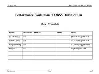
Performance evaluation of MU-RTS under OBSS environment Date: 2010-11-10 Authors:
Abstract • In this document, we first present some results of a statistical analysis of housing conditions in Japan, and show that more than 40% among all dwellings are the apartment houses. • Then, we show the numerical results of the number of OBSSs that can be happen in such an apartment environment. • Finally, we present simulation results of a simple OBSS scenario, and as an operator, we show the importance of a MAC protection mechanism for TGac.
Statistical analysis for the number of OBSSs according to “Housing and Land Survey*” in Japan • The Japanese governmental survey shows: • More than 40% houses are apartment houses (about 20 million in all of 49.6 million dwellings). • The average areaof floor space per dwelling in apartment house is about 520 ft2 (= 48 m2). • About 75% apartment houses are made of reinforced steel-framed concrete. • Operators’ perspective: • It is expected that 11ac standard will extend capacity of wireless home network which conveys network services (ex. on-demand video streaming services) to subscribers not only detached house but also apartment house users. It is important to examine the wireless environment in apartment house users *“Housing and Land Survey in 2008” done by Statistics Bureau in Ministry of Internal Affairs and Communications, Japan. http://www.stat.go.jp/english/data/jyutaku/index.htm
Statistical analysis for the number of OBSSs according to “Housing and Land Survey*” in Japan * Based on the “Housing and Land Survey,2008.” • Evaluation conditions: • Ave. dimensions of each apartment*: W / L / H = 16.5 / 33 / 10 [ft] • Tx power: 17 dBm@5GHz • Power loss of room wall and floor [1]: 13 [dB] • APs location: Each AP is placed at the center of each apartment house • Carrier sense level (which is equal to interference threshold): -82dBm@20MHz / -79dBm@40MHz / -76dBm@80MHz / -73dBm@160MHz • Bandwidth expansion to more than 40MHz causes one or more OBSSs in above apartment environment. • Some kinds of techniques to reduce the influence of OBSSs should be considered. **IEEE 802.11n channel model B – Residential. Interference level [dBm] in each apartment because of the AP in the top left apartment**. (AP) -56.33 -79.87 -48.72 -71.71 -93.53 -72.25 -89.20 -108.2 -91.42 -106.4 -123.2
OBSS issue • Consider frame transmissions using 80MHz (or 160 MHz) channel bandwidth. • As shown in previous slide, OBSS is likely to happen due to lack of channelswhen using 80MHz (or 160MHz) bandwidth. • This increases the frame collision probability at STAs which are placed in OBSS environment (especially, when APs are hidden to each other). • Moreover, TGac allows transmitting very large (up to 1 MB) A-MPDUs in one transmission attempt. • Therefore, the duration of a frame transmission tends to be longer. • This also may increase the frame collision probability especially at STAs in OBSS environment.
TGac background • DL MU-MIMO, which allows simultaneous frame transmissions to different STAs, is a key feature in TGac. • Multi-RTS [2], Multiple CTSs [3] schemes (hereafter called MU-RTS scheme) were presented in September 2010 meeting, and showed qualitatively the importance of MAC protection mechanism [4] for TGac. • Straw Poll results are summarised in page 3 of Ref. [5]. • Even though OBSS scenarios are complicated [6], TGac agrees to see how 11ac devices behave in OBSS environment [7, 8]. • So far, however, not that much evaluation results were presented. • In next slides we show some OBSS simulation results.
Frame sequence for MU-RTS scheme AP sends DATA frame only to STAs who replied with CTSs. The length of an A-MPDU depends on the current number of MSDUs buffered at the AP. AP can transmit A-MPDUs to up to 4 STAs simultaneously using DL MU-MIMO technique. When AP accesses to medium, it first transmits a CTStoSelf followed by MU-RTS [2, 3]. DATA (AP STA-N) DATA (AP STA-2) DATA (AP STA-1) AP STA-1 CTStoSelf … max (N) = 4 … … SIFS STA-2 MU-RTS CTS BA STA-N CTS BA … Each STA responds with a CTS frame if it is ready to receive DATA frame from the AP. All BAs are scheduled and transmitted in the same order as CTSs. CTS BA
Simulation conditions and scenarios • Consider only downlink UDP traffic • Two overlapping BSSs • Each BSS consists of one AP and 4 STAs • xSTAs (x=1,2,…,4) hear signal of the other • AP • APs are hidden or non-hidden to each other • STAs can receive any frames correctly unless there • are collisions (bit errors caused by thermal noise and • channel fading are not considered) • MPDUs for each STA are generated at the corresponding • AP by i.i.d. AP-1 AP-2 AP-2 AP-1 BSS-1 BSS-1 BSS-2 BSS-2 hidden AP non-hidden AP
2 2 hidden AP; 1STA hidden AP; 2STAs 1 1 3 3 1 1 4 2 2 2 2 2 2 3 3 3 3 AP-1 AP-1 AP-1 AP-1 AP-2 AP-2 AP-2 AP-2 1 1 1 1 4 4 4 4 3 3 4 4 4 BSS-1 BSS-1 BSS-1 BSS-1 BSS-2 BSS-2 BSS-2 BSS-2 hidden AP; 3STAs hidden AP; 4STAs
Parameter values Simulator: OPNET 15.0.A
Simulation results no hidden nodes, without MU-RTS no hidden nodes, with MU-RTS hidden AP; 4 STAs, with MU-RTS hidden AP; x STAs, with MU-RTS x = 1, 2, …, 3 hidden AP; 1STA, without MU-RTS hidden AP; 2STAs, without MU-RTS hidden AP; 3STAs, without MU-RTS hidden AP; 4STAs, without MU-RTS
Summary • We evaluate the performance of MU-RTS scheme. • MU-RTS scheme slightly degrades the system throughput when APs are known (non-hidden) to each other, because of the additional overhead due to MU-RTS and multiple CTSs. • When APs are hidden, MU-RTS greatly improves the system throughput. • Needs some sort of protection mechanism for TGac. • Frame sequences, Frame formats, and ACK mechanism (polled or scheduled) are TBD. • An example of frame format is described in [2]
References [1] Rec. ITU-R P.1238-3, "Propagation data and prediction methods for the planning of indoor radio communication systems and radio local are networks in the frequency range 900MHz to 100GHz," ITU-R Recommendation P Series, 2003. [2] Y. Morioka et al., “Multi-RTS Proposal,” Doc.: IEEE 802.11-10/1124r2. [3] T. Kaibo et al., “Multiple CTSs in MU-MIMO Transmission,” Doc.: IEEE 802.11-10/1067r0. [4] Y. J. Kim et al., “Considerations on MU-MIMO Protection in 11ac,” Doc.: IEEE 802.11-10/0335r1. [5] B. Hart et al., “TGac MU-MIMO Ad Hoc Minutes,” Doc.: IEEE 802.11-10/1161r0. [6] A. Ashley et al., “OBSS Requirements,” Doc.: IEEE 802.11-08/0944r7. [7] Y. Takatori, “Importance of Overlapped BSS issue in 802.11ac,” Doc.: IEEE 802.11-09/0630r1. [8] P. Loc et al., “TGac Functional Requirements and Evaluations Methodology Rev. 15,” Doc.: IEEE 802.11-09/0451r15.
Will it work with single legacy RTS/CTS? Upon receiving the CTS, AP starts transmitting DATA frame to multiple STAs using MU-MIMO. If AP does not receive CTS, it postpones the frame transmission and starts backoff. Retransmission procedure is TBD. AP sends a legacy RTS to one of STAs that the AP intends to transmit DATA frame. STA selection procedure is TBD. DATA (AP STA-N) DATA (AP STA-2) DATA (AP STA-1) AP STA-1 BAR BAR … max (N) = 4 STA-2 RTS BA CTS STA-N BA … … The STA responds with a CTS frame if it is ready to receive DATA frame from the AP. The STA which replied with CTS first acknowledges with BA. Other STAs do upon the reception of BAR from the AP BA
Will it work with single legacy RTS/CTS? Apartment environment Room #0 Room #2 Room #1 No! “Single legacy RTS/CTS” may not protect all STAs!! 3 1 3 2 1 3 2 AP-0 AP-1 AP-2 4 2 1 4 4 BSS-0 BSS-1 BSS-2
Will it work with single legacy RTS/CTS? • Pros: • No modifications to legacy Dot11 RTS/CTS mechanism • Less overhead • Backward compatibility • Cons: • Cannot protect all STAs within a single RTS/CTS exchange • DATA frame collisions still may occur
How about multiple legacy RTSs/CTSs with a round-robin manner? AP transmits DATA frame, using MU-MIMO, only to STAs who replied with CTS. AP exchanges legacy RTS/CTS with all STAs that it intends to transmit DATA. The order is TBD. Need to modify the Dot11 NAV settings. Because, STA-2 sets NAV and prevent transmitting frames if it receives third part RTSs or CTSs. DATA (AP STA-2) DATA (AP STA-1) DATA (AP STA-N) AP … max (N) = 4 STA-1 RTS#1 RTS#2 RTS#3 … … STA-2 CTS#1 BA#1 CTS#2 BA#2 STA-N … CTS#4 BA#2 Each STA responds with a legacy CTS frame if it is ready to receive DATA frame from the AP. All BAs are scheduled and transmitted in the same order as CTSs.
How about multiple legacy RTSs/CTSs with a round-robin manner? • Pros: • Works with least modification • Ensures full protection • Backward compatibility • Cons: • Needs some modifications on Dot11 default NAV settings • Large overhead