Download
1 / 19
200 likes | 368 Views
Multianode Photo Multipliers for Ring Imaging Cherenkov Detectors. Introduction Multianode Photo Multiplier Tubes R&D Results Light Scanning Facilities CERN Test Beam Conclusions. Franz Muheim University of Edinburgh. Osaka 29.7. 2000. LHCb Experiment.

E N D
MultianodePhoto Multipliers for Ring Imaging Cherenkov Detectors Introduction Multianode Photo Multiplier Tubes R&D Results Light Scanning Facilities CERN Test Beam Conclusions Franz Muheim University of Edinburgh Osaka 29.7. 2000
Particle Identification in Ring Imaging Cherenkov (RICH) Detector • LHCb is a experiment • Excellent particleidentification required: RICH detectors • e.g. 3 kaons in CP angle g decayBs0 -> Ds- K+ or Ds+ K- - K+K- • Large range: 1 < p < 150 [GeV/c] • Challenge: Photo detectors
Photo Detector Requirements • Photo detector area: 2.9 m2 • Single photon sensitivity (200 - 600 nm) with quantum efficiency > 20% • Good granularity: ~ 2.5 x 2.5 mm2 • Large active area fraction: 73% • LHC speed read-out electronics: 40 MHz • LHCb environment: magnetic fields, charged particles Options: MAPMT or HPD
Multianode Photo Multiplier Tube • 8x8 dynode chains • Gain: 3.105 at 800 V • Bialkali photo cathode, QE = 22% at = 380 nm • UV glass window, was borosilicate, QE dE increased by 50 % MaPMT
Quartz Lenses • MAPMT active area fraction: 38% (includes pixel gap) • Increase with quartz lens with one flat and one curved surface to 85% no lens lens 0 mrad lens lens 200 mrad 400 mrad
Laboratory Set-up • XY- Scanning table • Light source: Blue LED, single mode fibre gradient index lens (50 .. 100 mm spot size)
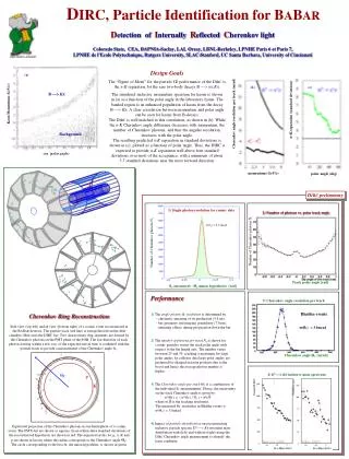
Laboratory Results Single channel spectrum (LED) Pixel scan with LED -900 V • Signal / pedestal s = 40:1 • Signal loss below 5 s cut: 11.5 % • Better focusing improves collection efficiency
3 x 3 Cluster Set-up • MaPMTs, quartz lenses • Bleeder board • 40 MHz Read-out: APVm chip
Test Beam Results With quartz lenses • Signal > 5 threshold, common-mode subtracted • Cherenkov ringvisiblelots of photo electrons • Some cross-talk • generated in electronics: APVm, ceramic Fan-in • 6000 events • HV: -1000 V
Photo Electron Yields With quartz lenses • Yield of p.e. corrected for • common-mode, • cross-talk, • a few dead pixels, • background 0.26 p.e. • Observe in data6.51 0.34 p.e. • Expect from simulation6.21 p.e. • Yield of different tubes • Signal > 5 threshold
Photon Yields No lenses Quartz lenses • Demonstrates lens effect yield ratio with/without lenses = 1.45
Single MAPMT Test Beam • CAMAC electronics • RICH 1 prototype Photo electron yield Good agreement
Charged Particles • Multiplicity from charged particles • [5..10] for for most angles • up to 30 for angles around 45o • small background • Charged particles traversing the lens & MAPMT produce background hits
Magnetic Field Tests • LED • Pin hole mask • -metal shield (0.9mm) • MAPMT tested with • Helmholtz coil • B = 0, 10, 20, 30 Gauss
Magnetic Field Results • B Transverse • MAPMTs are insensitive up to mag. fields of 30 G • Expect mainly By 30 G • B longitudinal • Sensitive to Bz 10 G gain loss, edge rows • Expect Bz< 10 G • -metal: • Extension d = 10,13, 32 mm • Reduces loss no structure (d = 32 mm)
Conclusions • Successfultest of 3x3 array ofMaPMTs • Quartz lenses and close packing work • Measured photon yield as expected • Demonstrated 40 MHz read-out • MaPMT works in LHCb environment • MaPMT fulfills RICH requirements MaPMT selected as LHCb backup photo detector due to high cost