Download
1 / 51
530 likes | 838 Views
Blood Pressure Tester. Group #5 Bianca Belmont CpE Brandon Sbert EE Raj Bose EE Ricardo Wheeler EE. Sponsored by: Texas Instruments Workforce Central Florida. Mentor: Herb Gingold. Project Description.

E N D
Blood Pressure Tester Group #5 Bianca Belmont CpE Brandon Sbert EE Raj Bose EE Ricardo Wheeler EE Sponsored by: Texas Instruments Workforce Central Florida Mentor: Herb Gingold
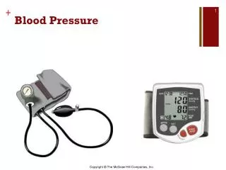
Project Description • Build an Automatic Blood Pressure Tester utilizing the Oscillometric Method (indirect) • Low Power • Wireless Display
Goals and Objectives • To be worn on upper arm • Battery powered • Simple user operation (one button device) • Integrate safe procedures into design • Implement wireless component • Calculate Blood Pressure reading (SYS DIA) • Transmit results wirelessly to display • Receive data from wireless module • Display Blood Pressure data • Error detection
Specifications • Power Supply 4 AAA rechargeable batteries (3v) • Power Life is 60 BP runs • Automatic using Micro motor (6V) / Micro Valve (6V) • Oscillometric • Accuracy of sensor plus or minus 3mmHg • Pressure range of 20mmHg to 280mmHg (cuff) • Adjustable cuff • Wireless range 1m <range> 2m • Display 138X110 grayscale, dot-matrix LCD
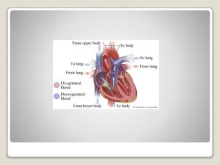
Blood Pressure Monitoring BP = SYS (high pressure contracting) / DIA (low pressure relaxed)
Exist many invasive and non invasive • methods • Similarity of 3 non invasive methods • all 3 use an occlusion cuff • all 3 record pressure values upon the turbulent re-entry of • blood to lower arm • all 3 inflate cuff to about 30 mmHg above average systolic • pressure to cut off blood flow to the lower arm • Palpitation – touch – direct method • Auscultatory – hearing – direct method • Oscillometric – algorithmic – non direct Blood Pressure Monitoring BP = SYS (high pressure contracting) / DIA (low pressure relaxed)
Auscultatory Method • Direct Method • Based on 5 auditory events (sound / silence) heard with stethoscope or microphone • Record meter pressure at first and last event to obtain SYStolic and DIAstolic pressure values BP = SYS / DIA
Oscillometric Method • Utilized in our device • Indirect Method • Cuff wall assumed one with the skin • Movement of skin due to turbulent blood flow pulses upon re – entry • Creates air turbulence in cuff • Algorithm uses two sets of data: • Originating from a mixed signal obtained by a pressure sensor connected • to an occlusion cuff • Calculates a systolic pressure and diastolic pressure for a blood pressure reading BP = SYS (high pressure contracting) / DIA (low pressure relaxed)
Oscillometric Method • Data set 1 • Cuff pressure vs. time • Data Set 2 • OnlyMAPMean Arterial Pressure obtained from signal • Average arterial pressure during one heart cycle • MAP = DIA + 1/3 (SYS – DIA) • MAPMean Arterial Pressure PEAK amplitude of signal Counterintuitive: MAP is the PEAK of a signal of re-entry pulses • SYStolic pressure is assumed to be the highest pressure in the heart cycle • SYStolic and DIAstolic points in timein relation to MAP
Motor • Model: P54A02R • Cylinders: 3 • Rated Voltage: DC 6V • Flow (No Load): 1.8L/min • Current (No Load): 170mA • Max Current: 290mA • Max Pressure: 95kPa • Noise: 50dB
Cuff • Model: D-Ring • Upper Arm • Standard adult cuff which has a circumference between 9-13 inches • Used for home-monitoring and self-application environments • It provides great flexibility, and it is light
Solenoid Valve • Model: KSV05B • Rated voltage: DC 6V • Rated Current: 60mA/45mA • Exhaust time: Max. 6.0 seconds from 300mmHg reduce to 15 mmHg at 500CC tank • Leakage: Max. 3mmHg/min from 300mmHg at 500CC tank.
Mechanical Valve • Maintains a slower linear deflation rate • Optimal for pressure sensor sampling: 160 – 80 mmHg (Cuff Pressure)
Pressure Sensor Freescale MPXV5050GP • Internal amplification • Low pass output to avoid noise • Required • 7mA constant current input • 5 V input Input Range 0 - 50 kPA ( 0 - 7.25psi) Output Range 0.2 – 4.7 Vout Transfer Function Vout = Vin * (0.018 * kPa + 0.04) 7.50061683 mmHg / 90mV BP = SYS / DIA = mmHg
Oscillation Signal • Systolic • Point in time when signal is 55% of the MAP amplitude • Diastolic • When signal has decreased by 85% of MAP amplitude
Experimenter Board • MSP430F5438 Experimenter Board • Is a development platform for the latest generation of MSP430 MCUs. • If features a 100-pin socket that supports the MSP430F5438 • It is compatible with many TI lower power RF wireless evaluation modules • Experimenter Board helps to learn and develop the F5xxx MCUs, which provides the lowest active power consumption, more memory and leading integration for applications such as energy harvesting and wireless sensing.
MSP430F5438A • MSP430F5438A Features: • 16-bit Ultra-low power microcontroller • 256KB Flash • 16KB RAM • High performance 12-bit analog-to-digital (A/D) converter • Real-time clock module • Language: C • Implementation: Code Composer Studio v5.1 • Schematics: TINA and WEBENCH Designer
Flowchart (Control Functions) Motor and MCU
Wireless EM Options • CC1101 EM – Sub 1GHz radio • CC2500 EM – 2.4 GHz radio • CC2430 EM – 2.4 GHz 802.15.4 radio • CC2530 EM – 2.4 GHz 802.15.4 radio
CC1101 EM • Protocal: RF • Frequency: 868 – 915MHz • Power: 3.2 V
Battery • 4x AAA batteries: 6V • Rechargeable Batteries • The advantages of using rechargeable batteries are many which include performance and durability • Power life 60 BP runs
Power Regulator for the Motor • Model: LM3488 • Switching Frequency (Max): 1000kHz • Switching Frequency (Min): 100kHz • Vin (Min): 2.95V • Vin (Max): 40V • Vout (Min): 1.26V • PWM Signal
Schematic of the Power Regulator for the Motor Efficiency 80%
Power Regulator for the Valve • LM3478 • Switching Frequency (Max): 1000kHz • Switching Frequency (Min): 100kHz • Vin (Min): 2.95V • Vin (Max): 40V • Vout (Min): 1.26V
Schematic of the Power Regulator for the Valve Efficiency: 77%
Power Regulator for the MCU • Model: TPS62122 • Vin (Min): 2V • Vin (Max): 15V • Vout (Min): 1.2V • Vout (Max): 5.5V
Schematic of the Power Regulator for the MCU Efficiency: 96%
Power Regulator for the Wireless • Iout (Max): 1A • Vin (Min): 4.5V • Vin (Max): 42V • Vout (Min): 1.285V • PWM Mode: Voltage Mode Control
Schematic of the Power Regulator for the Wireless Efficiency: 81%
Power Regulator for the Sensor • Model: Maxim LDO8877 • Vin (Min): 2.5V • Vin (Max): 6.5V • Maximum Output Current: 150mA • Constant Current Source: 7mA • Constant Voltage: 5V
Potential Issues • Data Transfer • Testing Regulators • Noise • Error Detection