Download
1 / 33
340 likes | 618 Views
NAVEDTRA 43904-1C. 107 CONTINGENCY OPERATIONS FUNDAMENTALS. References. References: COMSECONDNCDINST 3300.1, Rapid Runway Repair NAVFACINST 4423.1H, ABFC View Program NAVEDTRA 14270, Utilitiesman Basic Vol. 2, p 2-21 FM 5-277, Bailey Bridge. References.

E N D
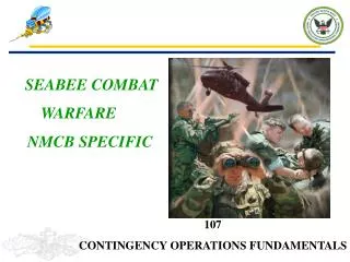
NAVEDTRA 43904-1C 107 CONTINGENCY OPERATIONS FUNDAMENTALS
References • References: • COMSECONDNCDINST 3300.1, Rapid Runway Repair • NAVFACINST 4423.1H, ABFC View Program • NAVEDTRA 14270, Utilitiesman Basic Vol. 2, p 2-21 • FM 5-277, Bailey Bridge
References • TM-08876A-23/2, Medium Girder Bridge, Marine Corps • AFMAN 10-219, Vol. 4, Rapid Runway Repair Operations • NAVEDTRA 14081, Equipment Operator, Basic • UFC 3-270-07 Unified Facilities Criteria O&M Airfield Damage Repair
References • CIN-710-1023, Airfield Damage Repair Crew Training Guide • Mabey Johnson User Manual • Training Guide for Command Post Bunker S-710-1017
RRR/ADR • PQS Question 107.1Describe the duties and responsibilities of the following Rapid Runway Repair (RRR)/Airfield Damage Repair (ADR) teams and state what type of equipment is necessary to perform their mission under Battle Damage Repair (BDR/RRR). • A. MOS [Annex C, pg 3-C-1 and 3-C-2]B. DAT [Annex B, pg 3-B-1]C. Crater/Spall [Annexes E, F, pp 3-E-1, 3-F-1] • Reference: COMFIRSTNCDINST 3300.1, CH III
MOS • MOS SelectionThe minimum operating strip is the smallest section of the runway required for launching and recovering an aircraft. Based upon the damage assessment data reported after an attack of the air base, the RRR command center must determine the locations of potential MOSs and estimate which one would require the lease apparent amount of time and effort to repair. The RRR command center may recommend possible MOS location alternatives to Station command center, but the Station command center will determine its final location.
DAT • DATDamage Assessment Priorities – The Station BDR/RRR plan should provide the damage assessment priority of the various Station facilities. The Battalion should integrate those priorities in its RRR plan and DAT assignments. - Runways and taxiways, aircraft maintenance facilities, aircraft parking, loading, and refueling areas. In these areas, all craters, spalls, and UXO must be reported.- Station command and control, and communication facilities.- Key utility substations or facilities.- Medial and decontamination facilities.- POL storage and pumping facilities
Crater/Spall • Crater/SpallCrater repairs consist of clearing debris from the crater, removing damaged pavement, backfilling the crater and installing Foreign Object Damage (FOD) cover. The debris clearing, pavement removal, and backfilling procedures are generally the same regardless of the FOD cover utilized. Spall – combination for rapid setting cements and pea grave. The recommended types of rapid setting cements are regulated set cement (Ideal Cement Company’s REG SET), or a magnesium phosphate cement (such as SET 45), or a high early strength type cement (such as PYRAMENT)
Contingency Operations • PQS Question 107.2 Describe the following methods of RRR/ADR:- Folded Fiberglass Matting (FFM)- AM-2 aluminum matting- Crushed stone repair- Crete mobile- Pave Mend
Contingency Operations • Folded Fiberglass Matting (FFM)- This procedure, which is currently the primary MOS repair method, involves the installation of an anchored FFM over a crater which was prepared with a layer of well-compacted crushed stone. Crater preparation is essentially identical to that used with the AM-2 matting system. Again, this is the principle method of RRR employed for MOS repairs at overseas MOBs (figure 5.4). Procedural details regarding FFM installation are provided in Technical Manual T.O. 35E2-3-1.
Contingency Operations • AM-2 aluminum matting is hand-assembled and anchored over the crater which was prepared with a layer of crushed stone. This repair surface is the most manpower intensive of the two primary RRR techniques
Contingency Operations • Crushed Stone Repair- The specific actions which must be accomplished during the crater preparation phase of the crater repair are: • Clearing debris from the crater diameter perimeter. • Determining the actual crater diameter versus the apparent crater diameter, i.e., the extent of crater pavement damage/upheaval. • Removing the upheaved pavement. • Removing large ejecta from inside the crater, as required. • Backfilling the crater with ballast rock, fill, or clean ejecta. • Backfilling the crater with crushed stone. • Compaction of the crushed stone. • Installing FOD cover.
Contingency Operations • The trailer-mounted crete mobile carries the cement, sand, and coarse aggregates in divided bins, mounted on the unit. The cement is carried in a separate bin, located across the rear of the unit, and the sand and aggregate are carried on each side of the unit. Water is carried in a single tank, mounted in front of the aggregate bins, and is pumped to the mix auger. Sand and aggregates are proportioned accurately by weight or volume and dropped simultaneously with a mixture of cement from the material feed system into the charging end of the mix auger/conveyor at the rear of the unit. At this point, a predetermined amount of water enters the mix auger. This action of the combined auger and paddle homogenizer mixes the ingredients and water rapidly, thoroughly, and continuously to produce a continuous flow of uniformed quality concrete. • The mixing action is a continuous process that can proceed until the aggregate bins are empty. On the other hand, mixing and delivery may be stopped at any time and then started again at the will of the operator. This permits production to be balanced to the demands of the placing and finishing crews and other job requirements.
Contingency Operations • PAVE MEND- Pavemend is a cementitious, rapid setting, semi-leveling structural repair mortar, ideal for rapid repair of roads and bridges, airport runways
Contingency Operations • PQS Question 107.3 Explain the fundamentals of a tent camp layout Reference: NAVFACINST 4423.1H, ABFC View Program, High-res camp layout, DWG 6028038
Tent Camp Layout • Tactical • sufficient space for command dispersion • concealment from ground and air observation • protection from bombing and strafing attacks • protection from mechanized attack • Sanitary • water supply • drainage • shade • access • site not occupied by other units in last 2 months
Latrines • Latrines must be 100 yards from the nearest natural water source and food service areas. The site should be reasonably near the user, but 50 feet from sleeping areas.
Garbage pits • Garbage is the solid or semisolid wet and dry wastes resulting from the preparation, cooking, and serving of food. Garbage has to be removed from the mess area before it causes bad odors or attracts rats and flies.
Garbage pits • The common method of garbage disposal is burial in a garbage pit. • A garbage pit should be a 4-foot square pit that is 4 feet deep. • It will service 100 people for 1 day. • A garbage pit must be at least 100 yards away from water supplies and 30 yards from messing facilities
CONTINGENCY OPS • PQS Question 107.4 Explain the purpose of maintaining operator logs for generators and boilers. [ref. c, ch. 2, p. 2-21; ref d, ch. 3, p 3-21.]
CONTINGENCY OPS • Daily operators logs are kept on some equipment. The main purpose for using operating logs is to continuously record data of equipment performance.
CONTINGENCY OPS • PQS Question 107.5 Discuss the following transportable bridges. - Bailey [ref. d, p. 1-5]- Medium girder [ref. 3, pp. 1-8 thru 1-13]- Mabey Johnson [ref. j]
Bailey • Bailey [ref. e, p. 1-5] • Through-type metal truss bridge with heavy timber decking, roadway carried between two main girders • Highly mobile and versatile bridge, can span a variety of gaps • Transported in 5-ton dump and 40 ton trailer • Quickly assembled by manpower, 30 – 40 personnel • 12’6” wide, can span up to 210’ • Configuration • Single / Single bridge, 100’ • Double / Single bridge 140’ • Double / Double bridge 180’ • Launched and de-launched via roller system
Bailey • Additional bays are added to counter balance during launching and de-launching • Components • Truss panel – form girder, 5’ x 10’ panel • Transom – main support, 10” x 20’ flange beam • Stringer – 10’ steel beam • Chess – 2” x 8” x 14’ wood decking • Rollers – launching & de-launching • Bearing & base • Ramps • Various pins, clamps, braces, tie plates, bolts, jacks, and carrying bars and tongs
Medium Girder • Medium girder [ref. f, pp. 1-8 thru 1-13] • MGB is a two girder deck bridge • 111/106 • Launched and de-launched via roller system and 5 ton dump Three types of MGB’s • Single story MGB • Double story MGB • Linked reinforced MGB • Transported to site via 5 ton dump & 40 ton trailer • Crew size 24 to 32 personnel
Medium Girder • Bridge is formed with 2 main girders from a number of panels pinned together • Roadway is formed by hanging deck units between girders and connecting ramps at each end • 13’ 2” wide bridge used for light vehicle loads
Mabey Johnson • The LSB combines standard off the shelf equipment with a range of purpose designed special equipment to meet the expectations of modern military loads and traffic expectations. • Panels —These are the main structural components of the bridge trusses. They are welded items comprising top and bottom chords interconnected by vertical and diagonal bracing. At the end of each panel, chords terminate in male lugs or eyes and at the other end in female lugs or eyes. This allows panels to be pinned together to form the bridge span. There are two different panels; a Super Panel and a High Shear Super Panel. The High Shear Super Panel is used at each end of the bridge span depending upon the loading criteria. • Chord reinforcement —These are constructed in the same way as the chords of the bridge panels and are bolted to the panels to increase the bending capacity of the bridge. For the LSB a heavy chord reinforcement is used.
Mabey Johnson • Transoms —These are fabricated from universal beams and form the cross girders of the bridge, spanning between the panels and carrying the bridge deck. The transom is designed for the appropriate loading criteria and for LSB is designed to accommodate MLC80T/110W. • Decks —Unlike wooden Bailey decks, the steel LSB decks are 1.05m x 3.05m and are manufactured using robotic welding technology. The decks are manufactured to have a long fatigue life and with durbar/checkered plate finish. The decks withstand both wheeled and tracked vehicles. • Bracing —A variety of bracing members are used to connect panels to form the bridge trusses and to brace adjacent transoms to the bridge. • Grillages and Ground Beams —On greenfield sites and when being used as an over bridge, ground beams are available that form an assembly which transmits all dead and live forces from the bridge into the ground. For a 40m (MLC80T/110W) bridge the ground bearing pressure is 200 kN/m2. The grillages are located on the top of the ground beams and accommodate the bridge bearings as well as the head of the ramp transom. • Ramps —The slope or profile of the ramps can be adjusted to allow for the passage of a range of civilian and military traffic. The length of a standard ramp at each end of the bridge is 13.5m. The ramps are bolted to the grillages and use standard deck units supported on special transoms. These transoms can be positioned at a variety of heights depending upon the set adopted with a special ramp post. The interface between the ramp and ground is a special toe ramp unit (1.5m)
CONTINGENCY OPS • PQS Question 107.6 Discuss heavy timber construction. - Bunker Assembly 14003 [S-710-1017, p 1-1-8]- Bridge Assembly 13202 [A-710-0044]- Tower Assembly 13630, 136040, 13650[S-710-1016, p. 1-1-12]
CONTINGENCY OPS • Bunker [Assembly 14003] • Total M-Hr = 891 • BU = 340 • SW = 40 • EO = 3 • CN = 508 • Bridge [Assembly 13202] • Total M-Hr = 560 • BU = 560 • Tower [Assembly 13606] • Total M-Hr =191 • BU = 127 • EO = 64