Download
1 / 38
400 likes | 609 Views
Explore catalyst properties using temperature programmed methods to understand physical and chemical changes under controlled conditions. This includes techniques like thermogravimetry, dilatometry, and gas analysis for catalyst pretreatment, reactant exposure, and desorption studies.

E N D
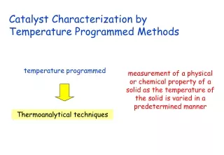
Catalyst Characterization by Temperature Programmed Methods temperature programmed measurement of a physical or chemical property of a solid as the temperature of the solid is varied in a predetermined manner Thermoanalytical techniques
Techniques dependent on weight changes Thermogravimetry Diff. Thermal analysis Techniques dependent on energy changes Diff. Scanning calorim. Thermoanalytical techniques Techniques dependent on dimensional changes DILATOMETRY Techniques dependent on evolved gases Temp. prog. desorption TPD, TPDE, TPSR Techniques dependent on gas analysis from chemical reaction TPRE, TP... Temp. prog. reaction Temp. prog. reduction TPR/TPO
temperature programmed desorption/decomposition rate • Pretreatment of the catalyst • Exposure to reactant gas • Desorption of physisorbed fraction • Heating of sample in an inert gas stream • Analysis of desorbed components coverage temperature time
M(s) + O2(g) MO(s) temperature programmed reduction/oxidation MO(s) + H2(g) M(s) + H2O(g) reduction rate • Pretreatment of the catalyst • Heating of sample in the presence of reducing or oxidizing mixture • Analysis of reductant or oxidant consumption Degree of reduction temperature time
temperature programmed reaction Coadsorption of two gases and heating in inert carrier Adsorption of one component and heating in reactive carrier gas Heating in reactive atmosphere containing reagents Temperature programmed methanation, hydrogenation, sulphidation, combustion…….
desorption vsdecomposition vsreaction CO CO CO CO CO CO TPD CO CO CO2 CO2 CO2 O O TPDE CO CO CO CO2 CO2 CO2 TPRE
information that can be obtained… • Characterization of reducibility of catalysts • Determination of binding energy of adsorbed molecules • Acidity • Kinetic of catalytic reaction (combustion, oxidation, methanation….) • Characterization of surface carbon deposits • Physical parameters (surface area, dispersion…)
Experimental: apparatus for TP studies introduction of reactants furnace and reactor detector concentration data acquisition time/temp.
Experimental: Detector and data acquisition Thermal conductivity detector Good for TPO/TPR Non specific gas analysis Concentration can be monitored continuously Mass spectrometer Concentration can be monitored continuously Specific gas analysis High cost Micro GC Concentration cannot be monitored continuously (delay 1-2 min.) Complex gas analysis Accurate quantitative evaluation
Because of large carrier gas flow rate relative to the quantity of adsorbed gas, extreme care must be taken in gas purification smaller particles decrease the possibility of intraparticle diffusional limitations and allow better thermocouple contact Too thin layer results in an irregular bed High heating rates result in better defined peaks, less time per run and less time for changes in flow rate and baseline High enaugh to avoid time delay between desorption/ reaction and detection Mass of sample should be kept to a minimum to avoid backpressure problems and temperature gradients within the bed Too deep results in back pressure and flow changes Low flow rate might cause diffusion problems small particles can create pressure drop or even fall through the reactor support Programmer must be able to maintain a linear profile, too high heating rates can result in diffusional limitations Probably best arrangement is to have roughly equal depth and width Experimental: 5. Practical consideration Gas flow rate Sample mass Sample particle size Geometry of the bed Heating rate Leaks and carrier-gas impurities
TPD-title Temperature Programmed Desorption Determining the strength of an adsorbate bond to the surface.
DEdes DESORPTION TPD-un activated Lennard-Jones Potential associative & un-activated adsorption potential energy DHads = -DEdes z DHads
DEdes DESORPTION TPD-un-activated Lennard-Jones Potential dissociative & un-activated DHads = -DEdes potential energy z DHads
DEads DEdes DESORPTION TPD-activated Lennard-Jones Potential dissociative & activated adsorption DHads =/= -DEdes potential energy z DHads
Temperature Programmed Desorptionfixed volume TPD-fixed volume 1 Temperature (T) / K gradient = dT/dt Time (t) / s p Pressure (p) / mbar Time (t) / s Q Coverage (Q) Time (t) / s
Temperature Programmed Desorptionfixed volume TPD-fixed volume 2 Temperature (T) / K gradient = dT/dt Time (t) / s p Pressure (p) / mbar Time (t) / s Q Coverage (Q) Time (t) / s
Temperature Programmed Desorptionfixed volume TPD-fixed volume 3 Temperature (T) / K gradient = dT/dt Time (t) / s p Pressure (p) / mbar Time (t) / s Q Coverage (Q) Time (t) / s
Temperature Programmed Desorptionfixed volume TPD-fixed volume 4 Temperature (T) / K gradient = dT/dt Time (t) / s p Pressure (p) / mbar Time (t) / s Q Coverage (Q) Time (t) / s
Temperature Programmed Desorptionfixed volume TPD-fixed volume 5 Temperature (T) / K gradient = dT/dt Time (t) / s p Pressure (p) / mbar Time (t) / s Q Coverage (Q) Time (t) / s
Temperature Programmed Desorptionpumped volume TPD-pumped volume 1 gradient = dT/dt Temperature (T) / K Time (t) / s p Pressure (p) / mbar Time (t) / s Q Q Coverage (Q) -dQ/dt Time (t) / s
Temperature Programmed Desorptionpumped volume TPD-pumped volume 2 gradient = dT/dt Temperature (T) / K Time (t) / s p Pressure (p) / mbar Time (t) / s Q Q Coverage (Q) -dQ/dt Time (t) / s
Temperature Programmed Desorptionpumped volume TPD-pumped volume 3 gradient = dT/dt Temperature (T) / K Time (t) / s p Pressure (p) / mbar Time (t) / s Q Q Coverage (Q) -dQ/dt Time (t) / s
Temperature Programmed Desorptionpumped volume TPD-pumped volume 4 gradient = dT/dt Temperature (T) / K Time (t) / s p Pressure (p) / mbar Time (t) / s Q Q Coverage (Q) -dQ/dt Time (t) / s
Temperature Programmed Desorptionpumped volume TPD-pumped volume 5 gradient = dT/dt Temperature (T) / K Time (t) / s p Pressure (p) / mbar Time (t) / s Q Q Coverage (Q) -dQ/dt Time (t) / s
Q Coverage (Q) -dQ/dt Time (t) / s Temperature Programmed Desorptionthe rate of desorption TPD-Arrhenius Use the Arrhenius expression for the rate of desorption Rdes : Rdes = - dQ/dt = [reactant]Aexp { - DEdes/R T } Concentration = coverage Arrhenius constant = frequency factor - dQ/dt = Qnexp { - DEdes/R T } equation I
Temperature Programmed Desorptionthe frequency factor TPD-frequency factor - dQ/dt = Qnexp { - DEdes/R T } equation I Reactive collisions per second = frequency of vibration For a vibration:- E = h n The energy in a vibration E = kT n= kT/h = ca. 1013 s-1 at 300K
gradient = A = dT/dt Temperature (T) / K T T0 t Time (t) / s Temperature Programmed Desorptionthe rate of desorption TPD-linear heating For a linear heating rate: T = T0 + At whereA = dT/dt (the heating rate) hence d1 /dt = A d1 /dT Therefore from equation I - dQ/dT = (Qn/A)exp { - DEdes/R T } equation II
TP -dQ/dtT -dQ/dT Temperature (T) / K Temperature Programmed Desorptionthe peak maximum TPD-peak maximum - dQ/dT = (Qn / A)exp { - DEdes/R T } equation II At the peak maximum, corresponding to a temperature TP - d2Q/dT2 = 0
Temperature Programmed Desorptiondifferentiation TPD-differentiation Differentiate - dQ/dT with respect to T to obtain - d2Q/dT2 Using d(U*V)/dT = U dV/dT + V dU/dT - dQ/dT = (n /A) {Qexp { - DEdes/R T }} constant - d2Q/dT2 = 0 = n /A {(Q DEdes/R T2 ) exp { - DEdes/R T } + dQ /dT exp { - DEdes/R T }} Therefore since at T=TP, - d2Q/dT2 = 0 : dQ /dT = Q DEdes/R TP2 equation III
TP -dQ/dtT -dQ/dT Temperature (T) / K Temperature Programmed Desorptionthe equation TPD-result dQ /dT = Q DEdes/R TP2 equation III - dQ/dT = (Qn / A)exp { - DEdes/RTP } equation II Combining equation III with equation II to eliminate the term dQ /dT : DEdes/R TP2 = (n / A)exp { - DEdes/R TP } equation IV From a measured value of TPone can calculateDEdes In the case of non-activated adsorption DEdes = -DHads
Temperature Programmed Desorptionthe calculation TPD-calculation DEdes/R TP2 = (n / A)exp { - DEdes/RTP } equation IV The easiest way to obtain – DEdes from TP is to use an iterative method on a re-arranged form of equation IV: DEdes/R TP2 = (n / A)exp { - DEdes/R TP } equation IV DEdes = R TP ln {n R TP2 / ADEdes ie.guess a sensible value for DEdes(eg 100 kJ mol-1 for chem.); substitute in RHS, calculate )Edes; Substitute new value in RHS, re-calculate, etc The solution quickly converges!
Temperature Programmed Desorptionthe coverage TPD-coverage The area under a TPD peak is proportional to the coverage. T2 ( - dQ/dT) dT a dQ T1 TP -dQ/dtT -dQ/dT Temperature (T) / K
Ru/Al2O3 Fischer-Tropsch Catalyst C + H2O CO + H2 CO + H2 HC / ROH CO – TPD CO preadsorbed at 303 K Flow of He 30 cc/min
CO-TPD from Al2O3 CO desorbed from Al2O3 is 1/3 of that desorbed from Ru/Al2O3
CO-TPD from Ru/Al2O3 :Effect of gas flow rate Re-adsorption!!!
TPR CO(ads) C(ads) + O(ads) slow step CO(g) + O(ads) CO2(g) Ru single crystal at low Pco No CO2 formation coking