Download

1 / 12
120 likes | 214 Views
Explore the system architecture, component details, and loss analysis of a Brayton Cycle designed for space application by Red Rover team. Components include turbine/compressor, heat exchanger, heater, regenerator, and system integration. The project timeline and discussion questions are also outlined.

E N D
Design and manufacturing of a brayton cycle for space application Red Rover Members: Lee Fuller Justin Mendonca Trever Pope Erik Sterbentz Nathan Bartel
Presentation Outline System Architecture Component Details Component Loss Analysis Tentative Fall Timeline Discussion Questions
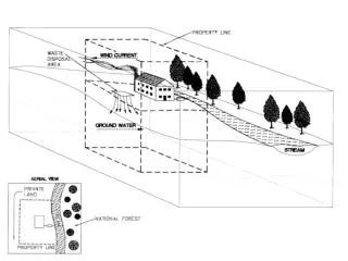
System architecture One system with valves to compare open to closed systems with or without regeneration.
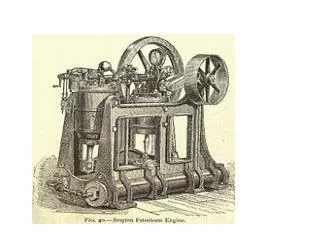
Turbine/compressor A turbine is needed to convert the fluid’s energy into rotational energy For this design, the turbine and compressor share a common shaft Blades will be interchangeable allowing for multiple test configurations Compressor is required to create a high pressure reservoir Both impulse and boundary layer effect type blades will be available for test configurations
Component Details Blade designs Boundary layer Driven Impulse driven • Paddle style impulse turbine • Effective with moderate efficiency • Moderate RPM range • Standard small compressor design • Tesla bladeless turbine utilized the boundary layer effect • High RPM range • Theoretical High efficiency • Testing of device
Component Details Heat Exchanger A heat exchanger is required in a closed cycle to provide a low temperature reservoir Open cycle Brayton systems do not require a heat exchanger The test apparatus includes both open and close cycles to gather data on each cycle performance The annular pipe heat exchanger is one design under development Submerging the compressor side cross fitting in an ice bath is another design concept Current heat exchanger designs are ideal for bench testing and do not reflect the final design concept
Component Details Heater Heat input is provided to the test system through a 1000 W heating element The heating element is contained within the housing shown to the right This drives the heat engine and provides the necessary input energy to extract work from the cycle
Component Details Regenerator The regenerator is an unnecessary component that increases the efficiency of the cycle Currently designs include an annular pipe concept show above, and a single pass shell in tube concept shown below Due to the systems low efficiency, the component may be necessary to meet project goals When active, turbine exhaust gas is diverted to preheat the compressor exhaust After the regenerator, the hot gas enters the heat exchanger or exhausts to the atmosphere
Component Details System Integration To minimize the system’s complexity, standardized components will be used Each pipe fitting will have 1” NPT threads Each temperature/pressure tap will have ½” NPT threads A common flange piece above will be used in every available location Additionally, the turbine and compressor share many common dimensions
Component Analysis • Head loss through each component • Heat loss in each component • Performance of heat exchanger • Efficiency of turbine, compressor and electric generator.
Tentative Fall Timeline Every Tuesday meet with advisors Every Thursday team meeting August 22 - Fall semester begins September 5 - End detailed design/fabrication September 6 - Begin testing September 30 - Have all purchasing completed December 16 - Present final results and report
Discussion Questions • Performance Testing Components: • Temperature • Pressure • Pressure gauges for high temperature application • Flow velocity • Volumetric flow rate gauge • Material Selection • Piping • Heat exchangers • Turbine blade material