Example - HW
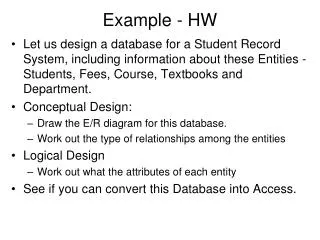
Example - HW. Let us design a database for a Student Record System, including information about these Entities - Students, Fees, Course, Textbooks and Department. Conceptual Design: Draw the E/R diagram for this database. Work out the type of relationships among the entities Logical Design

Example - HW
E N D
Presentation Transcript
Example - HW • Let us design a database for a Student Record System, including information about these Entities - Students, Fees, Course, Textbooks and Department. • Conceptual Design: • Draw the E/R diagram for this database. • Work out the type of relationships among the entities • Logical Design • Work out what the attributes of each entity • See if you can convert this Database into Access.
E-R Model of a student database Enrol in Courses Students has pay offer has Fees Textbooks Department
Types of relationships • Student and Course – many to many • Students and Fees – one to one • Textbooks and Fees – one to one • Department and Courses – one to many • Course and Textbooks – one to many • One to One (1------------m) • One to Many • Many to Many
Relationships • One – one relationship, an entity of either set can be associated with at most one entity of the other set; • Many – one relationship, each entity of the many side is associated with at most one entity of the other side; • Many – many relationships; place no restriction on the multiplicity.
Logical Design - Attributes • Students (Idnumber,surname,fname,gender,contact,sponsor • DepartmentCourses (CourseNumber,DepartmentId,Course Title,Coordinator) • TextbookFees(FeeCode,ISBN,Fee) • Departments(DepatmentId, Department name) • CourseTextbooks(ISBN, Course number, Title, Author, Edition) • StudentCourses(Idnumber,CourseNumber,FeesId)
Record Types • Now that we have the attributes of our entities, we will refer to them as record types. The record types are linked together by key fields which are highlighted in bold.
Physical Design • Once we have identified our record types and the relationship between the record type and the fields, the next step is to create tables. • To create tables we need a DBMS. • The DDL part of the DBMS enables us to create tables, alter, or delete a no longer needed table.
Table Student Data Definition Language (DDL) : Idnumber Char (10) NOT NULL Surname Char (30) Fname Char (30) Gener Char (1) Sponsor Char (30)
Instances of an E/R Diagram • E/R diagrams are a document for describing the schema of database, that is their structure; • A database described by an E/R diagram will contain particular data, which we call the database instance. • Specifically, for each entity set, the database instance will have a particular finite set of entities. Each of these entities has particular values for each attribute.
Multiplicity of Binary E/R Diagram • In general, a binary relationship can connect any member of one of its entity sets to any number of members of the other entity set. • Suppose R is a relationship connecting entity sets E and F, Then: • If each member of E can be connected by R to at most one member of F then we say that R is Many – One from E to F. • Note that in a many to one relationship from E to F, each entity in f can be connected to many members of E
Multiway Relationships • A multiway relationship in an E/R diagram that is represented by lines from the relationship diamond to each of the involved entity sets. • A studio has contracted with a particular star to act in a particular movie. Contracts Stars Movies Studios
Roles in Relationships • One role is original and the other is Sequel indicating the original movie and its sequel respectively. • We assume that a movie may have many sequels, but for each sequel that is only one original movie. • Thus the relationship is many to one from Sequel movies to Original movies. original Sequel-of Movies sequel
Attributes on Relationships • Sometime it is convenient, or even essential, to associate attributes with a relationship, rather than with any one of the entity sets that relationship connects. Salary Contracts Movies Stars Studios
Summary • Data Modeling • SDLC • What is Data Modeling • Application Audience and Services • Entities • Attributes • Relationships • Entity Relationship Diagrams
Database Modeling & Implementation Process Ideas E/R Design Relational Schema Relational Database
Elements of E/R Model • Entity sets • Attributes • Relationships
Data Modeling To draw a data model we follow the following informal Rules - Identify all the candidate entity types - Identify for each entity type the attributes involved - Identify for each relationship type the attributes involved - Put constraints on each relationship type (i.e (a) cardinality, (b) participation
Data Modeling - Entity • Two rules of “thumb” to help in identifying Entity and Relationship type are: - An Entity type corresponds to NOUN - A Relationship type corresponds to VERB
Data Modeling - Entity • Entity Sets - An entity is an abstract object of some sort and a collection of similar entities forms an Entity Set • E.g. * Employee entity set consists of the set of all employees • Department entity set consists of the set of all departments
Data Modeling - Attributes • Entity Sets have associated attributes, which are properties of the entity in that set E.g. Entity Set Movies might be given attributes such as title ( the name of the movie) or length (duration of the movie)
Data Modeling - Attributes • Most attributes are single – valued i.e. they have a single value for a given entity eg Age • However some attributes are multi-valued e.g. Tihe Certificate attribute for an employee can be multi-valued
Data Modeling - Attributes • Attributes which composed of several basic attributes are composite.
Data Modeling - Attributes • Attributes can also be null-valued e.g. tihe certificate attribute for a non graduate student take a null value • Null values can arise in two different contexts - when the attribute is not applicable - when the attribute is applicable, but the value is unknown • All entities that have the same attributes are classified as entity types
Data Modeling - Relationships Link or association between two or more entities - i.e. connections among two or more entity sets E.g. the fact that Ana works for the Accounting department represent a relationship work for between Ana and Accounting Department A relationship type is the set of all relationships between one or more entity types
Employee Works For Dept Data Modeling - Relationships
Data Modeling - Relationships • The Degree of a relationship type is the number of participating entity types • The set of all occurrences of WORK-FOR relationship make up the WORK-FOR relationship type
Recursive Relationship • Recursive Relationship • These are relationship types of degree 1 • E.g. an employee has a supervisor who is in turn is an employee SUPERVISOR EMPLOYEE
Cardinality • Constraints on Relationship Types Cardinality - specifies the number of relationships that an entity can participate in
Cardinality • Employee Manages Dept • The Cardinality of MANAGERS is said to be (1:1) between Employee and Dept
Participation • Participation - specifies whether or not every entity of a given entity type participates in a relationship type -if so participation is said to be total -if not participation is partial E.g. the participation of DEPT in MANGERS is total, whereas the participation of EMPLOYEE is partial
Weak Entity • Weak Entity An entity type that does not have a primary key of it own E.g. Consider the entity type DEPENDENT which is related to EMPLOYEE DEPENDENT (DependentName, Birth Date, Sex, Relationship)
Weak Entity DEPENDENT (DependentName, Birth Date, Sex, Relationship) Two dependents may have the same values for the above 4 attributes In such a case the two can only be distinguished by determining the employee entity to which each is related
Weak Entity • A weak entity type has partial key which is the set of attributes that can identify weak entities that belongs to the same parent (owner) entity. In the example not two dependents of the same employee have the same name so that DependentName becomes the partial key.
Entity Relationship Diagrams • E/R diagram is a graph representing entity sets, attributes, and relationships. • Elements of each of these kinds are represented by nodes of the graph • We use special shape of node to indicate the kind - Entity sets are represented by rectangles - Attributes are represented by Ovals - Relationships are represented by Diamonds - Edges connected an entity set to its attributes and also connect a relationship to its entity sets
E/R Model - DBMS • After designing a database using an ER model, how do we implement it in a DBMS? • We need to transform the ER model to the Logical Data Model supported by the DBMS that we choose
Logical Data Modeling • In General 3 Logical Data Models exist, namely: - Hierarchical Model - Network Model - Relational Model • We will look at 1 and 3, but concentrate on 3 as vast majority of DBMS use the Relational Model
Logical Data Modeling • Consider the following ER Model DIVISION DEPARTMENT Consists of Contains EMPLOYEE
Division 1 d5 d1 d7 d12 Logical Data Modeling • In a hierarchical DBMS, the above DB will be stored as a tree structure • A Query such as List all departments given a division number can be answered efficiently • However a query such as List the division that department 10 belongs to is very difficult to answer
takes Logical Data Modeling • Consider the following ER Model • This model will be implemented in a hierarchical DBMS as • Two problems with the above storage scheme • - Duplication of course data • - Very poor performance for queries such as – List all students taking a particular course say C2 • Due to these problems the Relational Model was proposed COURSE STUDENT S2 S1 C2 C4 C6 C1 C5 C3
E/R Model - Relational Data Model • Entity-Relationship (E/R) approach describe the structure of data • Relational Model– a single data-modeling concept the “relation” – a two dimensional table in which data is arranged.
Relational Model • What does it do? Gives us a single way to represent data as a two- dimensional table called a relation.
Relational Model Components • Entity :- Relation, table names • Attributes:- Column, or fields in tables • Schemas :- The name of the relation + the set of attributes for that relation • Tuples: rows of a relation, other than the header row containing the attribute names. • Domains: - relational model that requires each component of each tuple be atomic.
Relational Model • Entity – any object of interest in the real world Eg, a particular student, department, course etc… • An entity consists of attribute Eg. A student has attributes such as Reg #, Name, Address. etc. • One of these attributes is chosen as the Primary Key.
Relational Model • The model represents data in a database as a collection of tables • A relation has a name and a set of attributes e.g. R(A1, A2, A3, … An) • R is the name of the relation, A1, A2 …An are called attributes
Relational Model • Domain • atomic (that is it must be of some elementary type such as integer or string. It is not permitted for a value to be a record structure, set, list, array or any other type that can reasonably have its values broken into smaller component)
Relational Model • Domain Further assumed that associated with each attribute of a relation is a domain that is a particular elementary type. The components of any tuple of the relationship must have in each component a value that belongs to the domain of the corresponding column.
Relational Model • Each attribute Ai is defined on a domain dom(Ai) which is the set of values that Ai can take E.g. STUDENT (Reg#, Name, DateofBirth, Phone#) Dom(Reg#) = set of 4 digit numbers (0001-9999) Dom(Name) = set of all string of length 20 Dom(Phone#) = set of all 6 digit numbers
Relational Model Eg Movies ( title, year, length, flimType ) First component is a string, second and third component are integers and a fourth component whose value is one of the constants color and Black and White. * Domains are part of a relation’s schema.
Equivalent Representations of a Relation • Relations are sets of tuples, not list of tuples. Thus the order in which the tuples of a relation are presented is immaterial. (no matter how the tuples will be order- the relation will still be the same) • We can reorder the attributes of the relation as we choose, without changing the relation.