Download
1 / 16
160 likes | 327 Views
Ring to Main Linac and Low Emittance Transport. SLAC DOE Review Accelerator Breakout. Participants:.

E N D
Ring to Main Linac and Low Emittance Transport SLAC DOE Review Accelerator Breakout Peter Tenenbaum
Participants: RTML: Mike Church (FNAL), Eun-San Kim (Pohang), Sergei Nagaitsev (FNAL), Kellen Petersen (Cornell), Tor Raubenheimer (SLAC), Peter Schmid (DESY), Sergei Seletskiy (SLAC), Jeff Smith (Cornell), PT (SLAC), Andy Wolski (LBL), Mark Woodley (SLAC), Jiajun Xu (Cornell) LET: Linda Hendrickson (SLAC), Frank Jackson (Daresbury), J.K. Jones (Daresbury), Roger Jones (SLAC), Kiyoshi Kubo (KEK), Kirti Ranjan (FNAL), Daniel Schulte (CERN), Jeff Smith (Cornell), Nikolay Solyak (FNAL), PT (SLAC), Nick Walker (DESY), Glen White (SLAC), Andy Wolski (LBL) Peter Tenenbaum
What is the RTML? • What it says – the single-pass transfer line from the damping Ring To the Main Linac (thus RTML) • Includes • Post-DR collimation • Turnaround and trajectory feedforward • Control of polarization direction • Bunch compression • Pulsed extraction • For tuneup purposes or in case of machine protection fault • Plus a wide variety of diagnostics and correction devices • Emittance measurement, bunch length monitoring, dispersion and coupling correction, etc etc etc • Excludes • The extraction system from the damping ring (septa, pulsed kickers, compensating bend) • RTML begins when dispersion 0 after DR extraction Peter Tenenbaum
Situation at Snowmass 2005 • Basic configuration of RTML was decided • Two-stage bunch compressor • With energy gain between the stages • Turnaround for trajectory feed-forward • Other sub-beamlines, their roles and order in the RTML, decided • No actual design was available for adoption • None was developed at Snowmass • Too big a job, and Snowmass was too short a meeting Peter Tenenbaum
Since Snowmass • December 2005 • Snowmass WG1 writes RTML Baseline Configuration Document (BCD) • Required many decisions not explicitly taken at Snowmass, ie, how many pulsed dumplines, etc. • GDE selects Eun-san Kim and myself to be Area System Leaders for RTML • January 2006 – March 2006 • Construct complete lattice files (“decks”) for RTML • Nominal beamline plus pulsed extraction lines • Including requirements for tuning, all required configurations, etc. • March 2006 – present • Generate detailed component counts / specifications for costing Peter Tenenbaum
RTML Optics Peter Tenenbaum
RTML Footprint Peter Tenenbaum
RTML Costing and Technical Data All information is posted to the ILC RDR wiki site as soon as it is generated. RTML is in good shape to have first cost estimates at the Vancouver GDE meeting on 19-23 July 2006. Peter Tenenbaum
RTML Activities – Remainder of CY 2006 • Now – July 2006 • Complete first cost roll-up with RDR “Design Matrix” teams • August – November 2006 • Iteration on design • Technical experts have recommended a number of improvements • Likely to be many minor inconsistencies in current design • At boundaries with DR and ML • Tunnel layout adopted by CFS likely not exactly what RTML ASLs envisioned • Likely to be strong interest in cost reduction • Which will require design changes • Begin serious studies of emittance preservation and tuning • Started in a minor way already • RTML design includes lots of diagnostics and corrections • 1000 word essay on “Why this system will work” < 1 plot from a simulation which shows that it does in fact work • See the next part of my talk on LET work! • Write draft RDR chapter on RTML • November – December 2006 • Final draft of RDR chapter on RTML Peter Tenenbaum
RTML Activities – post-2006 • Support of ILC Technical Design Report • More advanced engineering development • More thorough development of technical specifications • Going to the next level in beam dynamics studies • Integration of RTML with the rest of the LET • Both static and dynamic studies • All planned and executed in conjunction with Americas Regional Team (ART) and the Global Design Effort (GDE) Peter Tenenbaum
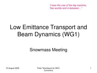
Low Emittance Transport (LET) • Study of emittance preservation and luminosity production in the single-pass beamline from DR exit to IP • Steering out static misalignments • Global corrections of aberrations • Feedback and feed-forward • Historically, concentrated on the main linac • Partially a side-effect of the technology choice • Strong recent efforts on BDS • Just starting to look at RTML Peter Tenenbaum
Situation at Snowmass 2005 • Quite a number of techniques for static alignment/steering control of linac • No serious effort at cross-checking • Person X tries to duplicate Person Y’s algorithm on simulation program with separate codebase • Different approaches to one technique could be qualitatively quite different • Example: some versions of DFS depend strongly on BPM resolution; others do not • Good progress in train-to-train (5 Hz) feedback simulations in linac • Static and dynamic BDS simulations less well developed • Collimator wakefields not yet well enough understood • Current predictive power is factor of 2 • Target is 10% • RTML studies nearly nonexistent • Well, duh, there was no lattice yet! • Multi-bunch effects in linac acceptable, ASSUMING: • Detuning of HOMs in 9-cell cavities meets specifications • Damping of HOMs in 9-cell cavities meets specifications • “Split-Tune” lattice with different phase advance per cell in x and y • Recommended 75° / 60°, adopted by linac designers Peter Tenenbaum
LET Progress in 2006 • Workshop at CERN in February • Got up to date on all the divergent results in our simulations • Started a serious effort to address them • Several simple exercises designed to find any actual bugs (or at least inconsistencies) in beam dynamics simulations • Found and fixed a few • Reference sets of misalignments • Eliminates one possible source of divergences • Began to really dig into the details of our algorithms • “I use DFS” doesn’t quite convey enough information! • Lots of detailed assumptions, etc. Peter Tenenbaum
LET work: Convergences Applying a common DFS implementation in 2 codes to 10 misaligned linacs Peter Tenenbaum
LET Work: BDS Achieved spot size dilution factors after applying static tuning algorithm Estimated hours of beam time required for tuning – not too different from FFTB and SLC FF experience Figures courtesy G. White, SLAC Peter Tenenbaum
LET Work – Remainder of CY 2006 and into Out Years • Additional cross-checking work • Document current status on LET website • More “Person X checking Person Y’s Results” • Most controversial: BPM performance requirements for linac tuning • Want to have 3 static tuning methods for linac, each simulated by 2 people independently • Start next steps • More serious integration of ILC regions • More serious integration of static and dynamic studies • These involve small amount of additional code development • Including beam-beam effect in lattice codes, etc. • Writing for RDR Peter Tenenbaum