Introduction to Energy Storage Systems
270 likes | 316 Views
Learn about the characteristics of energy storage techniques, from storage capacity to available power. Compare and select the best technology based on key criteria.

Introduction to Energy Storage Systems
E N D
Presentation Transcript
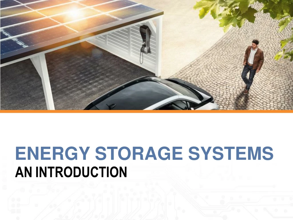
Energystoragesystems Date ANintroduction
Characteristics of energy storage techniques • Energy storage techniques can be classified corroding to these criteria: • The type of application: permanent or portable. • Storage duration: short or long term. • Type of product: maximum power needed. • It is therefore necessary to analyse critically the fundamental characteristics(technical and economical) of storage systems in order to establish comparison criteria are for selecting the best technology. • The main characteristic of storage systems on which the selection criteria are based the following. Storage Capacity This is the quality of available energy in the storage system after charging. Discharge is often incomplete. For this reason, it is defined on the basis of total energy stored, Wst (Wh), which is superior to that actually retrieved (operational), noted Wut (Wh). The usable energy, limited by the depth of discharge, represents the limit of discharge depth (maximum-charge state). In conditions of the quick charge or discharge, the efficiency deteriorates and the retrievable energy can be much lower than storage capacity. On the other hand, selfdischarge is the attenuating factor under very slow regime (see Fig. 16).
Characteristics of energy storage techniques Available power This parameter determines the constitution and size of the motor-generator in the stored energy conversion chain. It is generally expressed an as average value, as well as a peak value often used to represent maximum power of charge or discharge, Pmax(W)1. Depth of discharge or power transmission rate Energy storage is a slow process that subsequently must quickly release energy on demand. The power output, or discharge, can be a limiting factor called the power transmission rate. This delivery rate determines the time needed to extract the stored energy. The power must be available for delivery during peak hours, that is to say the amount of energy used, if significant, is representative of a non-optimum system design, or a fundamental limit of the storage apparatus.
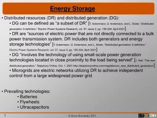
Electric Energy First, electricity is consumed at the same time as it is generated. The proper amount of electricity must always be provided to meet the varying demand. The second characteristic is that the places where electricity is generated are usually located far from the locations where it is consumed. Generators and consumers are connected through power grids and form a power system. Therefore it is helpful to store energy for later use. Energy can be stored by using various technologies:
energy storage technologies Chemical Energy Storage Mechanical Energy Storage Electrical Energy Storage Thermal Energy Storage Kinetic Energy Storage Low Temperature Energy Storage Electrostatic Energy Storage Magnet/current Energy Storage Potential Energy Storage High Temperature Energy Storage Chemical ES Electro-chemical ES Thermal ES Compressed Air Capacitors Aquifier LT-ES Batteries Pumped Hydro Fuel Cells Supercapacitors Cryogenic LT-ES Flywheels Superconducting Magnetic Energy Storage Solar Hydrogen Sensible Heat Storage Solar Metal Latent Heat Storage Solar Ammonia Solar Methane
Mechanical Energy Technology Type Open-loop Pumped Hydro Storage (Time Shift) Rated Power in kW 3,003,000 Duration at Rated Power 10:18.00 The Bath County Pumped Storage Station is a pumped storage hydroelectric power plant, which is described as the “largest battery in the world”, with a generation capacity of 3,003 MW[3] The station is located in the northern corner of Bath County, Virginia, on the southeast side of the Eastern Continental Divide, which forms this section of the border between Virginia and West Virginia. The station consists of two reservoirs separated by about 1,260 feet (380 m) in elevation. It is the largest pumped-storage power station in the world. Construction on the power station, with an original capacity of 2,100 megawatts (2,800,000 hp), began in March 1977 and was completed in December 1985 at a cost of $1.6 billion, Voith-Siemens upgraded the six turbines between 2004 and 2009, increasing power generation to 500.5 MW and pumping power to 480 megawatts (640,000 hp) for each turbine.
Electrical Energy Storage Supercapacitors The super caps shining point is C rate (or power). So if you hand pick the app where you need a high C rate at low ambients it might work to do a Cap/ battery Hybrid. They really don’t work in Tesla situation though where they have a huge battery so C rate is not that Critical and cycle life is not critical. Supercaps are great for fast discharging AND fast charging. Cyclelife is the most important part for storage! Graphene Supercapacitor
Electrical Energy Storage Ultracapacitors Ultracapacitors also last far longer, aren’t as temperature-sensitive (they’ve been used in F1 racing, after all), and don’t lose capacity as they age. Mazda führ I-Eloop-System ein, mitdem die beimBremsenentstehendeEnergie in einemKondensatorgespeichert Maxwell’s entire line of ultracapacitorproducts
Thermal Energy Cryogenic energy storage Cryogenic energy storage (CES) is the use of low temperature (cryogenic) liquids such as liquid air or liquid nitrogen as energy storage. HISTORY A liquid air powered car called Liquid Air was built between 1899 and 1902 but it couldn't at the time compete in terms of efficiency with other engines More recently, a liquid nitrogen vehicle was built. Peter Dearman, a garage inventor in Hertfordshire, UK who had initially developed a liquid air powered car, then put the technology to use as grid energy storage.
Thermal Energy Grid energy storage (Process) When it is cheaper (usually at night), electricity is used to cool air from the atmosphere to -195 °C using the Claude Cycle to the point where it liquefies. The liquid air, which takes up one-thousandth of the volume of the gas, can be kept for a long time in a large vacuum flask at atmospheric pressure. At times of high demand for electricity, the liquid air is pumped at high pressure into a heat exchanger, which acts as a boiler. Air from the atmosphere at ambient temperature, or hot water from an industrial heat source, is used to heat the liquid and turn it back into a gas. The massive increase in volume and pressure from this is used to drive a turbine to generate electricity Pilot plant A 300 kW, 2.5MWh storage capacity pilot cryogenic energy system developed by researchers at the University of Leeds and Highview Power Storage, that uses liquid air (with the CO2 and water removed as they would turn solid at the storage temperature) as the energy store, and low-grade waste heat to boost the thermal re-expansion of the air, has been operating at a 80MW biomass power station in Slough, UK, since 2010. The efficiency is less than 15% because of low efficiency hardware components used, but the engineers are targeting an efficiency of about 60 percent for the next generation of CES based on operation experiences of this system. The system is based on proven technology, used safely in many industrial processes, and does not require any particularly rare elements or expensive components to manufacture. Dr Tim Fox, the head of Energy at the IMechE says "it uses standard industrial components...., it will last for decades, and it can be fixed with a spanner."
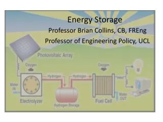
Chemical Energy: Fuel Cell A fuel cell is a device that converts the chemical energy from a fuel into electricity through a chemical reaction of positively charged hydrogen ions with oxygen or another oxidizing agent. Fuel cells are different from batteries in that they require a continuous source of fuel and oxygen or air to sustain the chemical reaction, whereas in a battery the chemicals present in the battery react with each other to generate an electromotive force. Fuel cells can produce electricity continuously for as long as these inputs are supplied. Comparison of fuel economy express in MPGe for hydrogen fuel cell vehiclesAvailable for leasing in California and rated by the U.S. Environmental Protection Agency as of August 2015 [23]
Chemical Energy: Fuel Cell Fuel cells for use in cars will never be commercially viable because of the inefficiency of producing, transporting and storing hydrogen and the flammability of the gas.
Sensible Heat Thermal storage Sensible heat thermal storage is achieved by heating a bulk material (sodium, molten salt, pressurized water, etc.) that does not change states during the accumulation phase; the heat is then recovered to produce water vapor, which drives a turbo-alternator system. The use of molten salt in the Themis station in France has made it possible to store heat economically and simplify the regulation of the solar panel (Fig. 5.)[8]. This system was designed to store 40,000 kWh of thermal energy, equivalent to almost 1 day of average sunlight, in 550 tonnes of fused electrolyte [8].
Worldwide installed storage capacity Figure 1 Worldwide Installed Storage Capacity for Electrical Energy
Comparison of energy storage technologies Table 1.1 - Summary of energy storage technologies
Comparison of energy storage technologies Table 1.2 - Summary of energy storage technologies
Flow Batteries PumpedHydro Metal-AirBatteries Hours PSB ZnBr VRB NaS Battery CAES High Energy Super Capacitors Long Duration Fly Wheels Lead-Acid Batteries Ni-Cd Energy Management Li-Ion Discharge Time at Rated Power Other Adv. Batteries Bridging Power High Power Fly Wheels Minutes Power Quality & UPS Seconds High Power Supercaps SMES 1kW 10kW 100kW 1MW 10MW 100MW 1GW Systems Power Ratings Figure 22 - Distribution of storage techniques as a function of their field of application [10]
10-3 hours (3.6 s) 1 hour 103 hours (41 days) 103MWh PumpedHydro Storage(PHS) SMES 102MWh LargeCAES 10MWh Power Output Micro SMES Low SpeedFlywheels High SpeedFlywheels 1MWh FlowBatteries 102kW 10kWh Figure 20 - Fields of application of the different storage techniques according to energy stored and power output[22] ElectrochemicalBatteries Small CAES 1kWh Supercapacitors 102MWh 1kWh 10kWh 102kW 1MWh 10MWh 103MWh 104MWh 105MWh Energy Store
Efficiency / Lifetime properties of storage technologies 100 Supercaps Li-ion Flywheel SMES Efficiency % NaS 80 FlowBatt. NiCd 60 100 1000 104 105 Lifetime / Charge-Discharge Cycles Figure 1 - Efficiency/lifetime properties
Storage Techniques 100% E.C. Capacitors Li-ion Fly Wheels 90% NaS FlowBatt. Pumped Hydro 80% CAES Lead-Acid 70% Efficiency (w/o power electronics) CAES efficiency Is for the Storage only Ni-Cd 60% 50% Metal-Air 40% 100 1,000 10,000 10,000 Lifetime at 80 % DoD - Cycles Figure 23 – Distribution of storage techniques as a function of energy efficiency and life expectancy [10].
Storage Techniques 10,000 High Power E.C. Capacitors High Power Fly Wheels Long Duration Flywheels Li-ion Ni-Cd 1,000 Lead-Acid Batteries NaS Battery Zinc-Air Batteries Flow Batteries Better for Energy Management Applications Capital Cost per Unit Energy – 5kWh-output (Cost/capacity/efficiency) Rechargeable Long Duration E.C. Capacitors Pumped Hydro 100 CAES Metal-Air Batteries Better for UPS and Power Quality Applications 10 100 1,000 3,000 10,000 300 Capital Cost per Unit Power - $/kW Figure 24 – Distribution of storage techniques as a function of investment costs per unit of energy [10].
Storage Techniques H. Ibrahim et al. Renewable and Sustainable Energy Reviews 12 (2008) 1221-1250 1247 1000 Output Energy Density (Input Energy Density x Efficiency) Metal-Air Batteries (Not rechargeable electrically) Large 300 Li-ion NaS Battery 100 Weight Energy Density – kWh / ton Ni-Cd 30 Lead-Acid Batteries Flow Batteries Smaller E.C. Capacitors Zinc-Air Rechargeable 10 Flywheels 10 100 300 30 1000 Volume Energy Density – kWh / m2 Figure 24 – Distribution of storage techniques as a function of their mass and volume densities of stored energy for small-scale applications [10].
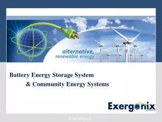
World's largest 2nd-use battery storage unit set to connect to the grid • 13-megawatt battery storage unit to connect to the grid in early 2016 • Levelling out fluctuations in the power grid as an active contribution towards the energy revolution • The world's largest 2nd-use battery storage unit will soon go into operation in the Westphalian town of Lünen and marketed in the German electricity balancing sector.
World's largest 2nd-use battery storage unit set to connect to the grid A special feature of this venture is the use of second-life battery systems from electric vehicles. In Lünen, systems from the second generation of smart electric drive vehicles are being incorporated into a stationary storage unit with a total capacity of 13 MWh. The process demonstrably improves the environmental performance of electric vehicles, thereby helping to make e-mobility more economically efficient.