Download
1 / 24
240 likes | 262 Views
This project aims to prepare FPP-SP data for scientific analysis by adapting existing tools developed for DLSP. Steps include dark and flat field corrections, polarization calibration, spectral adjustments, and more. The process is illustrated with data from the Swedish Solar Telescope to showcase fully calibrated results. Various challenges and considerations such as dark and flat field generation, spectral fringes, slit scan vignetting, and calibration matrix refinement are addressed to ensure accurate data reduction. Through meticulous analysis and corrections, the FPP-SP data is optimized for scientific exploration.

E N D
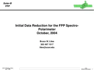
Initial Data Reduction for the FPP Spectro-Polarimeter October, 2004 Bruce W. Lites 303 497 1517 lites@ucar.edu
FPP Spectro-Polarimeter Data OBJECTIVE: The objective of the initial processing is to prepare the FPP-SP data in a form suitable for scientific data analysis. PROPOSED METHOD: I propose to adapt extensive data reduction tools developed for the Diffraction-Limited Spectro-Polarimeter (DLSP) at the National Solar Observatory/Dunn Solar Telescope to the FPP-SP. • DLSP is an instrument that evolved from the Solar-B Concept Model Spectro-Polarimeter • DLSP codes written in general way to be easily adapted to other spectro-polarimeters • Software both in IDL and FORTRAN (for speed of reduction)
Steps for FPP-SP Initial Data Reduction • Prior to analysis of science data: • Prepare the dark and flat field correction images • Prepare the polarization calibration matrix • For science data, the steps in order are: • Dark and flat correct • Apply polarization calibration • Remove spectral “skew” • Merge the two polarization beams • Fringe removal • Correct for spectral curvature • Compensate for residual I→Q,U,V crosstalk
Illustration of the Reduction Process I illustrate this data reduction scheme with the procedure as adapted to data from the new spectro-polarimeter at the Swedish Solar Telescope (SST). These data from 1 April 2006 demonstrate the correction “end-to-end” resulting in fully calibrated data.
Dark and Flat Field generation • Dark measurements from ground-based instruments are simple – just block the beam to the spectrograph. • FPP-SP darks are problematic, no shutter. • Flat field images: for FPP-SP must average many independent images of quiet granulation near disk center. • rms contrast of granulation expected to be ~15% • To achieve flats accurate to 0.5% rms, need ~900 independent measurements of granulation • Many coarse maps of quiet Sun required! • Flat procedure for spectra: obtain an average spectral profile from the average of flat images, then divide the spectrum by this profile to obtain the flat image. The multiplicative flat-field correction is the inverse of the flat image.
Multiplicative Flat Field Corrections Dark 0 Flat 0 Dark 1 Flat 1 • Sample dark, multiplicative flat field images for the FPP-SP obtained in sun tests on 13 June 2005. • Fewer flat images were needed than on orbit because the seeing was bad • Dark images are very uniform • Multiplicative flat images show little trace of spectral lines • Flat images scaled ±10% • Corrected image = (Raw-Dark)xMflat
SST Flat Field Correction Dark-corrected Flat Field Data Multiplicative Flat Field Correction
SST Dark Corrected Data Q I U V
SST Dark/Flat Field Corrected Data Q I • Opposite Q,U,V signatures in two orthogonal polarization image pairs U V
FPP-SP Calibration Matrices X-1 Residual Smoothed Original Spectral ROI 112-224 CCDSIDE0 CCDSIDE1
FPP-SP Variation of X over Slit Scan Range • Error Bars: polarization matrix requirement • Slit scan position -225 taken at low light level, so discarded
SST Polarization Calibrated Data Q I • Same Q,U,V signatures in two orthogonal polarization pairs • Symmetric Q,U • Antisymmetric V • Opposite seeing crosstalk in Q,U,V pairs U V
SST Skew Corrected Data Q I U V
SST Merged Data Q I V U Seeing crosstalk eliminated
SST Spectral Curvature Removed Q I V U
SST High Sensitivity Q,U,V Q I V U Q,U,V Grey Scale: ±0.5% Ic
Other FPP-SP Reduction Issues • Slit Scan Vignetting • Variation of SP throughput exists as a function of slit scan position. Also a 2-D variation vs. slit scan position (x) and distance along the slit length (y)??? • Polarized Spectral Fringes • Known to exist in the polarization calibration matrices • Smoothed over in the representation of the polarization calibration matrix as a function of (λ,y). • Refinement of the Calibration Matrix • It is possible to use solar observations of a sunspot umbra to refine the polarization calibration matrix. This will be difficult in view of variations of the matrix in (λ,x,y).
Slit Scan Vignetting Scan Mirror Step Number Scan Mirror Step Number 19 August 2004 NAOJ SP intensity vs. scan mirror position before pre-slit repair. FPP on OBU with solar feed. 26 May 2005 NAOJ SP intensity vs. scan mirror position after pre-slit repair. FPP on optical bench. Solar feed with telescope simulator.
Slit Scan Vignetting • Additional measurements: Careful observational study on-orbit of flat field observations taken over full range of slit scan positions • Analysis: Derive variation of intensity of these flat field observations as corrected by a flat field derived at the center of the scan range. Derive the normalization factor as a function of (x,y): ASP(x,y) • Corrections: Apply the normalization function ASP(x,y) to all FPP-SP map data. Applies equally to Stokes I,Q,U,V
FPP-SP Polarized Spectral Fringes • Spectral fringes are apparent at the few x 10-3 level (or less) in the calibration matrices • These fringes are not represented in the interpolated, smoothed representations of the calibration matrices • Will they show up in the final data on orbit? CCDSIDE1, Spectral ROI 0-112
Polarized Spectral Fringes An example of fringe removal from DLSP spectral data. One must examine final calibrated data from space to look for residual fringes of concern. Before Fringe Correction After Fringe Correction
Reduction Code Strategy • Preliminary analyses done in IDL • Calculation of flat field corrections • Calculation of vignetting corrections • Preparation of polarization response matrix corrections These corrections are determined only occasionally
Reduction Code Strategy • Routine Map corrections done with FORTRAN code spawned from IDL control routine • Application of dark/flat corrections • Polarization calibration • Skew removal • Merging orthogonal polarization images • Spectral curvature removal • Residual I→ Q,U,V crosstalk correction • Vignetting correction • Fringe removal?