Download
1 / 47
550 likes | 788 Views
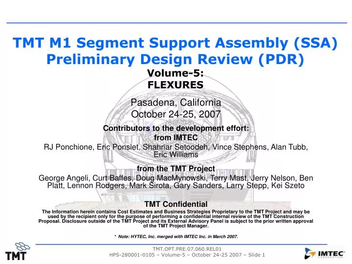
TMT M1 Segment Support Assembly (SSA) Preliminary Design Review (PDR) Volume-5: FLEXURES. Pasadena, California October 24-25, 2007 Contributors to the development effort: from IMTEC RJ Ponchione, Eric Ponslet, Shahriar Setoodeh, Vince Stephens, Alan Tubb, Eric Williams from the TMT Project

E N D
TMT M1 Segment Support Assembly (SSA) Preliminary Design Review (PDR)Volume-5: FLEXURES Pasadena, California October 24-25, 2007 Contributors to the development effort: from IMTEC RJ Ponchione, Eric Ponslet, Shahriar Setoodeh, Vince Stephens, Alan Tubb, Eric Williams from the TMT Project George Angeli, Curt Baffes, Doug MacMynowski, Terry Mast, Jerry Nelson, Ben Platt, Lennon Rodgers, Mark Sirota, Gary Sanders, Larry Stepp, Kei Szeto TMT Confidential The Information herein contains Cost Estimates and Business Strategies Proprietary to the TMT Project and may be used by the recipient only for the purpose of performing a confidential internal review of the TMT Construction Proposal. Disclosure outside of the TMT Project and its External Advisory Panel is subject to the prior written approval of the TMT Project Manager. * Note: HYTEC, Inc. merged with IMTEC Inc. in March 2007.
Contents • SSA Flexures - Design/Analysis • Design Load Combinations • Central Diaphragm (Lateral Support) • Requirements / Goals • Design description • Component sizing • Factor of Safety Summary • Rod-Type Flexures (Axial Support) • Requirements / Goals • Description • Mirror support rod flexures (27 ea) • Whiffletree Pivots (12 ea) • Actuator Rod Flexures (3 ea) • Component Design Loads & Sizing • Factor of Safety Summary • Lateral Guide Flexure • Requirements / Goals • Design description • Component sizing • Factor of Safety Summary
Flexures DESIGN LOAD COMBINATIONS
Central Diaphragm • Design Load Combinations: • Sources: DRD, Project Meetings, and Engineering Judgment • Load events are linear combination of multiple load inputs: Controlling for Diaphragm & Lateral Guide Flexure
Flexures • Requirements / Goals • Design description • Component sizing • Factor of Safety Summary CENTRAL DIAPHRAGM
Central Diaphragm • Design Approach: • Central diaphragm supports segment, reacting lateral gravity load • Low expansion metal diaphragm bonded directly to mirror: • No de-coupling flexures (low cost & compact) • Single machined part • no bonds, welds, or brazed joints that would interfere with the low CTE goal • Mirror has central pocket to position diaphragm in optimal location • minimize later print-thru • Material: Invar (or Inovar) • INOVAR (from IMPHY Alloys, France) is high-purity, low-Carbon version of Invar • Results in lower CTE and greater temporal stability compared to regular Invar • CTE = 0.65 PPM/C vs. 1.3 PPM/C for regular Invar • Note: we do not rely on the lower CTE, but hope to build it into the design • 0.250 mm thick epoxy bondline
Requirements & Goals • Requirements & Goals • Minimize diaphragm outside diameter: • Best optical performance & lowest cost • Minimize piston stiffness: • Decouple axial and lateral supports • Lateral strength characteristics: • Linear response through 1.5g static (no buckling during observing) • Elastic behavior – post buckled – to 4.5g static (3.0g * 1.5 FOS) • Torsional load characteristics: • Stiffness to achieve >8 Hz first clocking mode • Strength sufficient for robustness in handling • Flexure ID governed by Torsional goals: • (60mm center hub) [See backup slide] • 130mm Flexure OD chosen as compromise between size vs. stiffness: • Prefer smallest OD and pocket bore • Need compliance to decouple axial support
Requirements & Goals • Requirements & Goals, Cont. • Buckling controls design: • we choose ~2.0g nominal static buckling capacity • elastic behavior to 4.5g. (3.0 g with 1.5 FOS) • Other characteristics result from these decisions • Design Load Case • Mass of mirror segment subject to lateral gravity • 1g Lateral Load: Fr = 9.81 * 154.3kg = 1519 N
Diaphragm Trade Study • Design Trade-off • Two central diaphragm designs considered: • Traditional Flat diaphragm • Stress reducing diaphragm (Convolution and slotted rim) • Optical performance analysis guided down-select: • Flat diaphragm optical performance: • Lateral surface error: ~9.2nm RMS • Thermal distortion surface error = ~2.4nm RMS /C • Stress reducing diaphragm optical performance: • Lateral surface error: ~16nm RMS • Thermal distortion surface error = ~1.0nm RMS/C • JPL PSS analysis showed flat diaphragm to be better overall: • Prefer less high-spatial-frequency lateral distortion • Can tolerate more low-spatial-frequency thermal distortion. Flat Diaphragm Stress Relieving Diaphragm
Diaphragm Trade Study Note: Units are surface error • Optical Performance Comparison Flat Invar Diaphragm Stress Relieving Invar Diaphragm PV = 153. nm RMS = 9.22 nm PV = 252.4 nm RMS = 15.6 nm FOR REFERENCE: LATEST PREDICTIONS DIFFER SLIGHTLY (See Volume 3 for Latest Prediction) PV = 19.7 nm/◦C RMS = 2.4 nm/◦C PV = 4.4 nm/◦C RMS = 0.98 nm/◦C
Design Overview Slide Repeated from Vol-1 • Overview: Cross-Section View Diaphragm Adhesive Bond: Diaphragm to Glass Mirror Segment Adhesive layer Moving Frame
Design Details Information repeated from Vol-1 • Diaphragm Material: Invar (Inovar) • E = 130 GPa (18.85E6 psi) • Fty = 260 MPa (37.7 ksi) typical • a = 1.3 ppm/C 130mm Hub: 8.5mm thk. Flexure region 60mm Rim: 3mm thk. 150mm
Analysis Overview • Analysis Cases • Axial (Piston) load (1N unit load applied) • Linear-elastic small deflection analysis • we expect operational deflections of diaphragm to be on the order of microns • Lateral (Radial) load (1g dead weight applied: 1519N) • Linear-elastic small deflection analysis • Eigenvalue buckling • Nonlinear buckling load-deflection analysis • Determine post-buckling behavior to 4.5g • Torsional load (1N-m unit load applied to central hub) • Linear-elastic small deflection analysis • Assess torsional stiffness and segment clocking natural frequency • Eigenvalue buckling • assess susceptibility to damage due to handling loads (no significant torsional loads anticipated) • Thermal Mismatch (DT = 1◦C Unit Case) • Linear-elastic small deflection analysis • Eigenvalue buckling analysis • CTE mismatch between glass and diaphragm can result in diaphragm buckling
Analysis Methodology 1g (linear) • Typical analysis results • Lateral load: Nonlinear analysis Lateral Load-Deflection 2.7g (initial buckling) 4.5g (remains elastic) 1g 2g 3g 4g Note: Deflections magnified 50x
Thickness Sizing Study • Nonlinear analysis performed to select thickness: • 0.350mm chosen as nominal thickness (0.350+/-0.025mm) Nominal Design
Analysis Summary • FEA Results • Considering diaphragm thickness tolerance (+/-0.025mm) Adhesive: EA9313 E = 296 ksi, a = 45 PPM/C, n = 0.15
Effect of Thickness Variation • FEA Results for Baseline Design (t=0.350+/-0.025mm) • Nonlinear response – post buckling • Min, Nominal & Max thickness (machining tolerances)
Central Diaphragm - SUMMARY • Summary • Flat regular invar diaphragm sized for TMT application: • Design Parameters: • Rim OD=150mm, ID=130mm, 3mm thick • Flexure OD=130mm, ID=60mm, thickness=0.350+/-0.025mm • Center Hub 60mm OD x 8.5mm thick • Material: Invar or Imphy Alloys INOVAR (ultra pure Invar) • Requirements and goals satisfied: • Axial stiffness minimized • effect on optical performance verified at system level • Lateral: • Linear behavior through 1.7g lateral (with min thickness) • Elastic through 4.5g lateral (post buckling) • Bond max shear stress <150 psi at 1g • Sufficient torsional stiffness (12 Hz.) and strength (>350 Nm) • Thermal buckling >95C
Flexures • Requirements / Goals • Design description • Mirror support rod flexures (27 ea) • Whiffletree Pivots (12 ea) • Actuator Rod Flexures (3 ea) • Component sizing • Factor of Safety Summary ROD TYPE FLEXURES
Requirements • Rod flexures are required to • have some minimum axial stiffness • resist column buckling • have good lateral compliance • have good strength to resist all anticipated loads • be corrosion resistant • be low cost • be easy to install • We consider all of these factors when making design decisions • System stiffness requirement affects rod-flexure design: • Piston stiffness requirement: 12N/micron - with rigid actuator and mirror cell • wind rejection • The design process is iterative – this is a snapshot
Loads and Factors of Safety • Requirements, cont. • Rod flexures subject to a variety of load conditions as defined previously: • Required factors of safety (based on engineering judgment) Table repeated form slide-4
Flexure Design Overview • Design Overview • Rod-Type Flexures Mirror support rod flexures Pivots Next Slide Cross-Section View
Flexure Design Overview • Design Overview • Pivots Moving Frame Large Wt Triangle MF- Large Triangle Pivot Flexible Region: 3.0mm OD x 45mm long Material: 17-4 PH Triangle-Triangle Pivot Flexible Region: 1.5mm OD x 20mm long Material: 17-4 PH Sheet Flexure Mid-Plane Small WT Triangle
Flexure Design Overview • Design Overview • Mirror support Rod Flexure Design Repeated from Vol-1 Invar Puck Mirror Vent Hole Flexible Region: 2.1mm OD x 143mm Long Rod Material: 304 CD M3 Hex Nut, 3 places Vent Hole WT Triangle
Flexure Design Overview • Design Overview • Actuator Rod Flexure Design Slide Repeated from Vol-1 Knurled Flexible Region: 7.23mm OD x 115mm Long
Flexure Design Overview • Design Overview • Rod flexure lengths are constrained by the system design. • The desire for a compact system drove the fundamental layout • Mirror rods: • For buckling controlled design mounted to back surface of mirror, longer is better • Diminishing returns after 80mm • Length only important because we attach to back-surface • Mid-plane mounting independent of length fro buckling critical • We choose 143mm for convenience • Triangle-Triangle Pivots • With nested whiffletree triangles, the available space is limited • Maximum length for this arrangement is 20 mm • Moving Frame to Large Triangle Pivots • Length constrained to 45mm • Actuator flexure • Maximum length is 115 mm with this arrangement
Flexure Design Overview • Design Overview • Given the System stiffness requirement 12N/micron • Axial Stiffness budget guides flexure sizing • We desire bending compliance, but require axial stiffness • Balanced design implies maintaining certain axial stiffness values for rod flexures • Triangle-Triangle Pivots: Kaxial > 17 N/micron • MF to Large Triangle Kaxial > 30 N/micron • Actuator Flexure Kaxial > 40 N/micron
Flexure Design Overview • Material Selection: • No brittle materials • All flexures must be corrosion resistant • Plating not preferred • additional process • thickness of certain features critical • Mirror rod flexures (27): • Long and slender makes these difficult to heat-treat • Choose Cold-drawn 304 stainless steel • Fty = 250 ksi (1724 MPa) • Triangle Pivots (all 12): • Too large in diameter for 304CD, must heat-treat these • Choose 17-4 PH H1025 (Lower cost precipitation hardened stainless steel) • Fty = 145 ksi (1000 MPa) • Actuator rod flexure • Subject to fatigue cycles and high stress levels (bending due to actuation) • 10 cycles/night * 365 * 50 = 182,500 cycles • Choose Titanium 6Al-4V Annealed (no heat treat required – avoids distortion) • Fty = 125 ksi (862 MPa)
Sizing Calculations • Flexures are sized considering the effects of every load combination on each flexure separately. • The controlling load cases are determined considering these loads in conjunction with the Factors Of Safety and Stiffness goals. • We begin with Unit Cases: • FEA predicts loads from the following components: • Mirror Rod Flexures (27) • Whiffletree Triangle-Triangle Pivots (9) • Whiffletree Moving Frame-to-Large Triangle Pivots (3) • WH Actuators (21) • Actuator Rod Flexures (3) • Unit Load Cases Analyzed by FEA • Operational Configuration (Mirror supported by SSA) • 1g-x,y,z • DT = +1C • 21 Warping Harness Actuators • Shipping Configuration (PMA inverted and supported by mirror) • Transportation g-x,y,z • Warping Harness Loads (derivation presented in WH presentation) • 100% Combined Case (Operational correction of Zernikes) • Hard-stop fault condition (Controller fault drives actuators to their limits)
Sizing Calculations • We calculate a Component Load Matrix which contains the magnitudes of loads on each flexure subject to the unit loads • Absolute values taken (loads are +/- in sign) • Worst of gx or gy load case used to envelope the lateral load cases • Example:
Sizing Calculations • We then multiply the Load Combination Matrix by the Component Load Matrix to determine loads on each flexure for every load case. • We then extract the max value acting on each flexure-type for every load combination and use these to size the components • Imposed displacements are added to the component loads to determine max stress conditions • Actuator rod subject to tip deflection and rotation due to full tip/tilt • Deflection = 1.0mm, Rotation = 0.5 deg (from 1.2m design – conservative) • Other flexures subject to 0.1mm offsets (deflections) • After tuning the sizes, the flexures meet requirements: • see next page
Sizing Calculations • Calculation of Rod Flexure Stress, Bucking and Factors of Safety
Results Summary • Flexure Design Summary • Flexure designs meet requirements • Risks: • Distortion (bending) of flexure during machining or heat treating • Tolerances on tapered pin/holes may cause misalignment
Flexures • Design approach • Requirements / Goals • Design description • Component sizing • Factor of Safety Summary LATERAL GUIDE FLEXURE
Design Approach • Design Approach: • Lateral Guide Flexure: • Supports Moving Frame (hence segment), reacting lateral gravity load • Accommodates piston/tip/tilt actuation • Provides center-of-rotation close to the mirror • minimizes segment de-center due to tip/tilt motion • Several design options explored: • Flat diaphragm – too stiff in piston • Stacked Diaphragms - too soft in lateral • C-Flexures – too soft in lateral • Three blades oriented at 120 degrees – too stiff in piston • Circular diaphragm with OD convolution - Suitable
Requirements & Goals • Design Requirements & Goals • Accommodate piston compliance: • Elastic response at 3.0mm piston • Lateral (In-plane) Stiffness: 50 N/µm (Derived) • Lateral vibration mode: ~85 Hz SDOF fits with system requirement of 35 Hz • Piston Force: <150 N at 3.0 mm (Derived/Chosen) • Limit the nonlinear load each actuator must apply to piston 3.0mm to 50N ea. • Buckling and Stress Factors of Safety • FSy = 2.0 • FSbu = 1.5 • Design Loads: • 3g Lateral: 5739N (Supported mass = 195 kg) • Required buckling strength: 8600 N Lateral • 3g * 1.5 FOS • Fatigue Cycles: • assume 10 cycles/night * 365 * 50 years = 182,500 cycles
Design Details Guide Flexure Mirror Segment Moving Frame Clearance hole for Mirror Support Rod Flexure
Construction • Construction • Fabrication Method TBD • Formed or Machined – lowest cost part that meets requirements • Baseline Material: • Aluminum: 7075-T651 (assumes machined part) • Yield strength: 462 MPa (67 ksi) • Fatigue stress limit for 1E6 cycles ~172 mPa (25 ksi) • R = -1.0 (fully reversed bending) • Kt = 1.0 (no notches, peak stress not at stress concentration) • 1E6 cycles is 5x on lifetime • Material CTE chosen to match Tower and Moving Frame • Avoid thermal buckling
FEA • Geometry • Outer bolt radius = 161 mm • Inner bolt radius = 39.5 mm • Rim thickness = 10 mm • Thickness = Design Parameter • Loads: • Radial: 1913N (1g) • Piston: 3.0 mm
FEA Results Baseline Design F 1st Buckling Mode
Nonlinear Analysis • Initial Stiffness = 23 N/mm • Stiffness at 3 mm of piston = 92 N/mm • Load at 2.5 mm ≈ 100 N • Load at 3.0 mm <150 N
Guide Flexure Summary • Flexure provides adequate lateral and torsional stiffness • K_lateral = 52.6 N/mm (Exceeds 50N/mm goal) • Stress levels are acceptable • Yield Strength: FSy = 462 / 59.8 = 7.7 (2.0 required) • Fatigue: Piston stress (50.4MPa) well below fatigue strength (172MPa) • Buckling load exceeds design goal • 3g Survival/Handling Load Case: FSbu = 9190 / 5739 = 1.60 (1.50 required) • Piston force acceptable: • F3.0mm = 144.5N (less than the 150N goal)
Acknowledgements Acknowledgements: The TMT Project gratefully acknowledges the support of the TMT partner institutions. They are the Association of Canadian Universities for Research in Astronomy (ACURA), the California Institute of Technology and the University of California. This work was supported as well by the Gordon and Betty Moore Foundation, the Canada Foundation for Innovation, the Ontario Ministry of Research and Innovation, the National Research Council of Canada, the Natural Sciences and Engineering Research Council of Canada, the British Columbia Knowledge Development Fund, the Association of Universities for Research in Astronomy (AURA) and the U.S. National Science Foundation.
Flexures BACKUP SLIDES
Central Diaphragm Sizing • Hub sizing study • Original work performed for 1.2m segment • Showed that small hub diameters are weak and soft in torsion. • 60mm hub diameter chosen as a good compromise
Rod-Type Flexures • TMT Mirror Rod Flexure Design Options
Rod-Type Flexures • TMT – Keck Rod Flexure Comparison