Download

1 / 36
360 likes | 469 Views
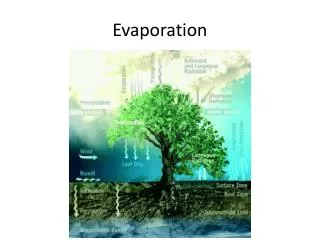
Explore various models depicting the isotopic composition in the hydrologic cycle, including marine atmospheric models, evaporation processes, and land surface interfaces. Witness how isotopic values evolve through the cycle.

E N D
Figure 1: Hydrologic cycle in relative flux units (100 units equals marine evaporation). Figures have been rounded up. (adapted from Chow 1964)
Figure 2: The Marine atmosphere model of Craig and Gordon (1965) assuming a closed cycle for the marine domain. The d values refer to the 18O; d2H values are shown in parenthesis. The water transport fluxes are given in amounts of liquid water equivalent in units of metre/year.
Figure 3: The Craig-Gordon isotopic evaporation model. I and B signify the surface interphase zone and the atmosphere boundary layer respectively; x = (1 – hN) and y = (aV/LRL – hNRA) where hN is the relative humidity normalised to the saturated vapour pressure at the temperature and salinity conditions of the water surface and dA its isotopic composition; d`A’ is the isotopic composition of the air moisture at the boundary layer of the diffusive sub-layer and h`’ is the corresponding relative humidity.
Mean marine precipitation according to the Craig and Gordon marine atmospheric model Figure 4: The marine evaporation process in terms of the d diagram
Figure 4a: Change in isotopic composition accompanying evaporation of surface waters starting from composition dp on the MWL. The residual waters are enriched along the EL (Evaporation Line). The evaporate dE then mixes with the original air (da) to yield a d-excessive vapour d’a which can give rise to precipitation of composition d’p. The slope of the evaporation through the stagnant air layer (eg soil or stomate) is about ½ that of the open water evaporation line. Where the atmospheric vapour and the water body are in isotopic equilibrium the the slope of the EL is dependent on humidity and equals a value of ~ SEL = 4.2. In other cases the slopes differ as shown in Figure 4b. (see Gat WRR-7: 980-993 (1971)
Figure 5: Scheme of the atmosphere/land surface interface based on Gat and Tzur (1976). The back flux of water into the atmosphere by evapo transpiration consists of three variants: 1) evaporation from open-water bodies with isotope fractionation; 2) tranpiration from plants without isotope fractionation; 3) periodic evapotranspiration from reservoirs where selection by season is based on rain amounts.
Figure 6: Adaptation of the Craig and Gordon model for marine atmosphere to include the terrestrial part of the hydrologic cycle. The double loop indicates that isotopic equilibrium is assumed.
Figure 7a: Scheme of the land surface interface based on Figure 5 for temperate climate. Different climate settings differ principally in the relative importance of surface run-off in the water cycle.
Figure 7b: Scheme of the land surface interface based on Figure 5 for semi-arid climate. Different climate settings differ principally in the relative importance of surface run-off in the water cycle.
Figure 7c: Scheme of the land surface interface based on Figure 5 for arid climate. Different climate settings differ principally in the relative importance of surface run-off in the water cycle.
Figure 8: Isotope change along components of the hydrologic cycle. A broken line signifies evaporation through a stagnant air layer whereas the full line refers to fractionation of open surface waters.
Figure 10: The effect of evaporation from falling droplets beneath the cloud base when the evaporate is recycled into the cloud.
LOCAL RELATIONSHIP AIR – MASS EQUATION NAME MODELSCHEME Figure 11: The change of the isotopic composition of air moisture during precipitation for the Raleigh scenario and 3 cases where the Raleigh process is not obeyed.
Figure 12: The march of isotopic values during a rain spell in four stations in Israel ranging from the sea coast to a mountain range of elevation > 1000m (29 Dec 82 to 6 Jan 83). The distribution of rain amounts during the sampling intervals is shown on top. Value of the d excess parameter (per mille) for the GNIP station Bet Dagan samples is given on the top of the bottom diagram
Figure 13: Comparison of dD and d 18O snail body water in relation to environmental waters. Data on mean rainwater values are from Gat and Dansgaard (1972). Isotopic values for water in equilibrium with humidity were calculated for 10oC and for 20oC based on humidity isotope measurements in Rehovot. The data show the importance of dew in the water balance in this system (from Goodfriend et al, 1989).
Figure 14: The enrichment of isotopes by evaporation from a limited capacity reservoir, applicable to water intercepted on the canopy and in the top soil layer.
Figure 15: Through flow and stem flow isotopic compositions as a result of canopy interception from data collected by Leopoldo [1981]. The data collected from different precipitation events are all normalised to a value of d = 0 for the precipitation event of each day. The averaged value for all stemflow and throughflow events, respectively is shown by the encircled point.
Figure 16: Oxygen-18 profiles of soil moisture in a field in Sweden. The letters correspond to identified peaks in summer and winter precipitation.; the recharge rate is about 260 mm/year.
Figure 16a: Isotope profiles in unsaturated soils. (a) Experimental steady state profile; (b) Field profile from an unvegetated arid zone sand dune (from Allison et al)
Figure 17: Top: The averaged range of isotopic composition of rain and run-off in a desert environment (Negev, Israel) Bottom: The isotopic signature imposed on desert groundwaters by different recharge pathways
Figure 18: The evolution of the isotopic composition of a number of desert showers (Sde Boker, Negev desert) and the isotopic composition of the resulting local run-off and regional flood. It is evident that the flood selects the most depleted part of the rainfall.
Equal evaporation/transpiration curves for winter with data points Figure 20a: The build up of isotopic enrichment in the Okavango Swamp, Botswana (winter, this diagram, and summer) as a function of salinity increase for different ratios of the evaporation to total evapotranspiration flux (Dincer et al 1979)
Equal evaporation/evapotranspiration ratio curves for summer with data points Figure 20b: The build up of isotopic enrichment in the Okavango Swamp, Botswana (winter and summer, this diagram ) as a function of salinity increase for different ratios of the evaporation to total evapotranspiration flux (Dincer et al 1979)
Figure 21a: Schemes of different combinations of evaporation and transpiration areas on the isotopic composition of the residual run-off. FP – the rain flux; z – the lake runoff fraction ie the fraction of inflow to the lake which runs off as surface flow; y – the total run-off fraction of the basin; x – the fraction of precipitation on the basin which is re-evaporated from the lake; and t – the fraction of precipitation which is recycled by transpiration (from Gat and Matsui, 1991.)
Figure 21b: The isotopic composition of precipitation (dP) and run-off (dy) for different ET systems (shown in Figure 21a) with y = 0.5 and h = 0.75. The insert shows the difference between dy and dp as a function of x (see Fig 21a) .
FRACTION OF (NET) WATER AMOUNTS WHICH APPEAR AS SURFACE RUNOFF Figure 22: Fraction of (net, ie corrected for evaporation loss) water amounts which appear as surface runoff, scaled from the site of precipitation, for temperature and arid climates (A); Figure (B) shows the percentage of water with subsurface history in the surface waters.
Figure 24: The isotopic composition (dL,SS ) of lakes with varying through flow rates and the equivalent value of the evaporate (dE). x = Fin/E where x = 1 obviously refers to the terminal lake, where all the inflow is lost to evaporation under steady state conditions.
Figure 25 Isotopic composition of rainwater and water vapour in the plain of Israel. Area A represents the isotopic composition of water vapour in equilibrium with typical convective rain of isotopic composition dp. Area B represents the composition of air masses which are closer to equilibrium with the Mediterranean Sea water. Loops f, h and m represent the composition of water vapour where the evaporation of rainwater occurs under fractionating, half fractionating (ie where half the flux is fractionated and the other half evaporates without fractionation) and non-fractionating conditions (ie where there is complete evaporation of raindrops), respectively [calculated according to the Craig and Gordon (1965) equations. Data points are shown for an increase in humidity of 20%, 40% and 60% for each of these conditions and C represents the range of conditions for these evaporated waters. MWL = meteoric water line and EL = evaporation line. The figure to the right shows the waters which would be in equilibrium with the vapours shown in the lower left. Dotted lines connect the points for relative humidity increases (Dh/h) of 0.2 and 0.4 respectively
Figure 26: The isotopic composition of precipitation in the Amazon Basin in comparison with the expected Raleigh rainout curve (from Salati et al 1979)
Figure 27a: The continental scale isotope balance:- The bird-eye’s view: Under a simple and ideal Rayleigh-rainout scenario the atmospheric moisture is depleted in the heavy isotope content commensurate with the loss of moisture by precipitation during a continental passage, following more-or-less a “Meteoric Water Line” with a constant d-excess. Due to the eco-hydrological interactions at the land surface part of the incoming precipitation is re-evaporated, either directly from open water bodies and canopy intercepted precipitation pools, from the topsoil layer or through the intermediary of plants as transpiration. The latter, i.e. the transpiration flux, returns the water essentially unfractionated to the atmosphere with the result that there is an apparent reduction in the degree of the Rayleigh rainout effect, which can be measured by comparison of the isotopic buildup in the atmospheric waters compared to the expected buildup based on the precipitation amounts. Evaporation from open water surfaces returns a fractionated flux, where the residual surface waters are enriched and the evaporated moisture depleted in the heavy isotopes of Hydrogen and Oxygen, following an “Evaporation Line” rather than the “Meteoric Water Line”. Under such circumstances the degree of recycling of the moisture due to this mechanism can be quantified by recording the change in the d-excess parameter in the downwind atmospheric waters, In the more arid environment with its endorheic runoff regime, more and more of the runoff is lost by evaporation as the scale of the basin increases [6], often terminating in highly saline lakes or sabkhas. In contrast to the situation described above, the evaporative signature of a decreasing d-excess is then accentuated in the runoff with increasingscale of the system whereas the effect on the atmospheric moisture diminishes as a higher and higher fraction of the surface water is evaporated. The distinction between the evaporation and transpiration fluxes based on the water and isotope balances, which is a very valuable diagnostic tool under humid and semi-arid conditions, cannot then be indiscriminately applied in the more arid environment.
Figure 27b: The Continental Scale Isotope Balance The view from below The surface and sub-surface runoff on a basin or continental scale carries the integrated precipitation isotope signal, alas at times with a considerable time delay. As the geographic scale increases the effect of the evaporative signature of the watershed processes is diluted in the continual runoff by the precipitation in excess of the infiltration capacity of the soils. In the more arid environment with its endorheic runoff regime, more and more of the runoff is lost by evaporation as the scale of the basin increases, often terminating in highly saline lakes. In contrast to the situation in the atmosphere, the evaporative signature of a decreasing d-excess is accentuated in the runoff with increasingscale of the system.
Figure 28: Schematic representation of three air-sea interaction models; namely: a) the box moisture build-up model; b) the lake model; and c) the leeside convective model